1kW smps project (based on MicrosiM design)

Silvio

Well-known member
@badboy_6120

From what I can see is that the current trafo is not producing enough current and hence not coupling enough magnetic field to the core. Due to this when putting the load resistor all the voltage produced in the secondary is dropping a lot. Well if you found a way with what you did then leave it like it is as long as its working.

One other problem that I faced in my smps is that it was hard to start and without a small inductor in the output (1.5uH) it will trip due to it seeing a dead short when charging the secondary caps. I have 4000uF on each rail. In my version I am using ETD49 and now I added feedback and is regulated to 60v-0-60v. It can peak up to 1200 watts and can run at 900 watts continuous all day.

You did not say what is the peak output voltage (no load) you have on your smps. What is the output voltage at 1500 watts?

Be careful if you are using halogen bulbs or heater elements as these tend to draw a lot of current during warm up and a 400 watt halogen can easily draw more than 10-15 from a cold start for a second or so. You will find that when starting on load it may work ok due to the soft start but if you had to load it while the smps is running then it might trip your overload protection.

You can take a look at the load test on my video. Here I was using the first bobbin wound for 90-0-90volts peak and the maximum load given here is around 1100 watts not regulated. Now I changed it and wound it for 75v peak without feedback. Adding feedback brings the need for an output inductor which in my case I used a common mode choke with a double 15uH and regulation to 60v,
The video can be found on this link https://www.youtube.com/watch?v=18l-plvqkdU

regards Silvio
 
Very good looking smps you have there
Here's the outputs :
170V in idle (No load)
155.7V @ 2.35A >> 365W
147 @ 4.5A >> 660W
139 @ 6.12A >> 850W
133 @ 7.67A >> 1020W
130 @ 9.13A >> 1180W
 

Silvio

Well-known member
@badboy_6120
Today I seen the revised schematics and did some calculations on the number of turns wound on the trafo, I do not know the frequency of operation as I did not come across it in the blog.
According to my calculations it seems that the smps should run at 50Khz and a flux density of around 1200 guass with the number of turns given in the schematic. I also was wondering why did they use an ETD59 which is rather a large core for this power. Half bridge topology cannot give more than 1500 watts as there will be a lot of losses due to the trafo running at 155v and losses tend to rise sharply above this power.

With the same core that you are using if it is an ETD 59 and N87 material it will give around 3.5 to 4 KW of power if run in full bridge mode. In my version I have an ETD49 N87 core and runs at 65 Khz and can safely peak 1200 watts and withstand it for 5min on and 2min off with the heatsink temperature climbing up to around 50deg. I got metal on the fets and diodes and heat dissipation is very good with that cpu heatsink that I fitted.(fan on)

My voltage drop is around 19% of the peak value when fully loaded at 1200w. That is from 150v it will go down to 125v with a 240vac input. The inductor in the output also create a small voltage drop and I will loose another 5 to 6v in it so the output will go down to approx 120v.

Regards Silvio
 
Yes I'm using ETD59 as my transformer because of heating problem
My etd49 transformer is not standard and it got really hot in idle condition (about 65 degrees)
That's why I'm using etd59
Also my wending didn't fit on an etd49
 

Silvio

Well-known member
Oh I see why now. I was wondering how much power your sub woofer consumes, It really must be a big one for dedicating such a powerful smps for it. What is the switching frequency used in your smps? Did you see the output noise? Why not post a picture of the smps for us to see?
In my version I made the heat sink in such a way that the breeze from the fan cools also the trafo and the output inductors.
 

MicrosiM

Administrator
Staff member
Oh I see why now. I was wondering how much power your sub woofer consumes, It really must be a big one for dedicating such a powerful smps for it. What is the switching frequency used in your smps? Did you see the output noise? Why not post a picture of the smps for us to see?
In my version I made the heat sink in such a way that the breeze from the fan cools also the trafo and the output inductors.

I agree, we need some pictures and some videos. Unless this is a commercial stuff?
 
It's 50khz
I'm still working on pcb and as soon as I finish the test with amplifiers I will build the final pcb and share it here
I test this smps with a 200W RMS amplifier but it was on 8 ohms and my new amp will drive 4 ohms subwoofer
On 8 ohms @ 200w the sound was gread and I couldn't hear any hum in idle condition with no input
But on 4 ohms @800w I'm sure I have to have some good filtering on smps as it draw more current
 
Hey guys
I test my first amplifier and it sounds amazing
Now I'm facing new problem
My output negitive voltage see more drops than positive side when smps goes under load (about 10V)
I even remove amplifier and test it with a Heater Element but same result
I test my two transformers with different turns but the problem still there
Voltages of two rails are the same in idle but when I increase load I see more drops between Negitive than positive(according to output ground)
Is something wrong with output diodes?
 

Silvio

Well-known member
@Badboy

It is normal for a little center tap wonder. You should load the output with similar loads between positive and center ground and negative and center ground. Then you will know if you really have center tap wonder.

You should show us your setup and we can see what you have. This could be also the case of an imbalanced output inductor if you have one. 10 volts is rather a high difference. 1 to 2 volts is rather normal.
 
The thing is that when I connect smps to my amplifier I see more drops on negitive rails even both rails are drawing the same amount of current
If I have uneven loads than I should have more current on negitive rails that causes the voltage drop
Am I right?
The voltage drops is not the same in different loads
The more load I connect to output the more voltage drops on negitive side
Can this problem be from output diodes?
 

Silvio

Well-known member
@Badboy
If the voltage drop on the negative side is there for one of these reasons.
1) It could be the secondary windings on the trafo are not symmetrical and one of them may have a looser coupling than the other thus the voltage drop on one side.
2) If the output diodes are of the same quality and rating they should perform the same on both rails.
3) Are you using an output inductor? if so you may have different inductance on one of the rails

Try the test with similar loads on the output as I explained before and you will surly know if the unbalance is coming from the smps or because of an unbalanced load.

Again 10v is a very large discrepancy and something is not right. You can also try to load the AC section on the secondary winding before the diodes and check output there. This will give you a quick answer if its from the transformer or something else.
 
It turns out the problem was from the output diodes because when I changed the output diodes the problem go away and now both chanel drops are about the same with less than 1 volt difference

Thank you silvio for answering
 

Silvio

Well-known member
@badboy, as far as capacitors its best to have both sides but its best to have 2 to 3uF per watt on input and 1000uF per amp on the output for audio purpose if you really need a good punch.

By the way we did not see anything from your end, This thread is intended to all those who wish to learn and its important to show your work

Thanks for your replies.

I haven't share any picture yet because I'm still on prototype and as soon as I finish all my tests, I'm going to make my own PCB and will share it here
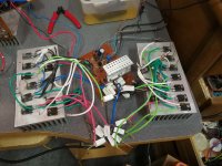
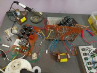
Here is 2 pictures of my prototype SMPS & AMP
AMP.jpg SMPS.jpg

*Don't let the pictures fool you because both of those are working great*
 

behrad

Member
hi to all
i have some questions about 1kw ludo smps
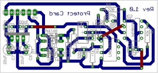
1:in bottom pic what is multiturn and R1 value?
protect.jpg
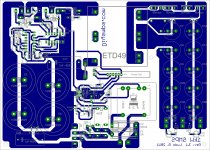
2:what is relay voltage and current in ludo smps?
zzz.jpg
3:does work ludo smps without protector circuit?
4:plz tell me core etd49 Winding instruction detailed
 

Silvio

Well-known member
@ Behrad

Multiturn preset can be 500 ohm or 1k ohm

Relay coil voltage is 12vdc current rating is 5 to 10A according to input current absorbed by smps

Yes it can work without protect card, I suggest you do it, it can save you a lot of trouble later.

Winding detail is in post #93 in this tread

Regards Silvio
 
Top