1kW smps project (based on MicrosiM design)

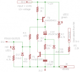
View attachment 5616View attachment 5617View attachment 5618I have 2x680uF in series at primary (eqivalent 340uF).
Trafo ratio is n=3. The secondary side capactance is 4x1000uF (2000uF per rail).
I am getting ripple at secodary side exacly 2.8Vp-p.

After adding another 2 caps 1000uF/200V at each rail (i have 840uF equivalent capacity at primary side), I am getting around 2,45Vp-p ripple at secondary (measured from V- rail to V+ rail).

badboy --> that is why I am so surprised that you have only around 100mV ripple at secondary (screanshoot no6 50mV/div).

I must do some more investigation at my board.


for screenshots number 1 to 3 I set oscilloscope in 50X mode (10X switch on the probe and 5X on the oscilloscope) and I forgot to set it back for screenshot no6 (50mV/div)
So with 540W load I have 4V p-p ripple not 100mv

8x0.2x5x10x50x10^-3 = 4V
 

borysgo2

New member
badboy
Thanks a lot, that is making a lot of sense to me now.
The additional capacitance at primary helps a lot.

Regards Peter
 
badboy
Thanks a lot, that is making a lot of sense to me now.
The additional capacitance at primary helps a lot.

Regards Peter

happy to help

by the way 3V p-p is with 5A output current, as I said earlier I changed the main transformer to a lower voltage for some test (56-0-56)

good luck
 
Last edited:

stewin

Member
It's possible with a minor rework. However I don't recommend using it to power up a PWM controller (use what you have on your schematic instead).

thanks sir i used the circuit on schema .it worked well , i have used mje340 instead of tip50 all is cool and well. but i still need to coil the main former properly . will post results
 
Hi guys

I connect the smps to a 200W amplifier (4 0hms) and I have some lousy noise on amplifier output without any input signal
56877.jpg

I even short cut the amplifier's input but the same noise with a little attenuation exist on the output

with traditional power supply (50Hz transformer and 22000uf on each rail) I have a nice and clean output without any input signal
here's the schematic of my current amplifier
Amp.jpg
 
What channel/probe did you use?
Hi "Jagd.Panther"
It's on channel two
Volts/Div = 50mv
Time/Div = 5 us
probe attenuation is on 1X


is that +-400mV on amp out?

If you're talking about the peak to peak of sparks, yeh that's right


I added some snubbers to smps and now the sparks on amplifier's output is less than 80mV peak to peak

The snubbers are :
1nf/10 ohms 2W on each IGBT's collector-Emitter
2.2nf / 10 ohms 0.25W on each main transformer secondaries
 

tsalz

New member
Anyone have a complete parts list for the 2.1 version? Some parts such as R4,R5,C21,C22 are not specified. I read the entire thread and never found anyone mentioning this or a complete BOM.
 

ikemhla

New member
1kW smps project(Based on MicrosiM Design)

A warm Hi to you all.

I am new to this forum.

I am interested in building this smps. Can someone help me and guide me through he whole process.

I find this project very fascinating. I need +75 and -75 volts for my amp.

Thank you all in advance for your help.


Regards

Ike
 

stewin

Member
hi all i found this protect schema on the web by schutzschaltung . i tried it and it works well with my smps .
but i wanted to increase the current limit to about 8 amperes or even 15 amperes . where can i adjust??

:(
 

Attachments

  • schutzschaltung protect with led indicator.png
    schutzschaltung protect with led indicator.png
    8.5 KB · Views: 211
  • sg3525-smps-schutzschaltung.gif
    sg3525-smps-schutzschaltung.gif
    19.4 KB · Views: 254
  • sg3525-smps-schutzschaltung 2.jpg
    sg3525-smps-schutzschaltung 2.jpg
    27.1 KB · Views: 163
Top