2 kwts discreet class d need help

norazmi

diysmps Senior Member
Ok stewin, i do change D5 with mur120 because today i`ve tested with +/- 65 vdc, and 4148 always dead after sometimes.. lol. did you power up using smps? i`ve use smps sg3525 and ir2110 and i lower the voltage about +/- 35 vdc, everything is ok. So i raise the output dc at +/- 65 then magic happens hahahaha... D15 dead... change to second time, also dead lol... so i change again to mur120 and its ok, butttt... the aux transistor blown :D . regarding D5, do u mean 12v zener diode? On your schema is D11? do u have yahoo messenger? or gmail? so we can chat for more clear..

regards.
 

norazmi

diysmps Senior Member
One more stewin, try remove 10k resistor R16 and R23. and for your question, yes both diode D17, D18, D16 and D11, help to improve thd a little.
 

norazmi

diysmps Senior Member
Stewin this is result without 10k resistor.


Fourier components of V(out)
DC component:0.371649

Harmonic Frequency Fourier Normalized Phase Normalized
Number [Hz] Component Component [degree] Phase [deg]
1 1.000e+02 3.277e+01 1.000e+00 -158.63° 0.00°
2 2.000e+02 1.946e-01 5.938e-03 -2.86° 155.78°
3 3.000e+02 1.011e+00 3.084e-02 66.30° 224.93°
4 4.000e+02 1.082e-01 3.303e-03 2.31° 160.95°
5 5.000e+02 3.944e-01 1.204e-02 102.23° 260.86°
6 6.000e+02 6.258e-02 1.910e-03 11.70° 170.34°
7 7.000e+02 2.198e-01 6.708e-03 145.77° 304.40°
8 8.000e+02 3.896e-02 1.189e-03 14.51° 173.14°
9 9.000e+02 1.271e-01 3.880e-03 -164.65° -6.02°
Total Harmonic Distortion: 3.474877%


Fourier components of V(in)
DC component:9.87225e-010

Harmonic Frequency Fourier Normalized Phase Normalized
Number [Hz] Component Component [degree] Phase [deg]
1 1.000e+02 2.000e+00 1.000e+00 -0.00° 0.00°
2 2.000e+02 1.635e-09 8.176e-10 -55.38° -55.38°
3 3.000e+02 2.685e-09 1.343e-09 44.19° 44.19°
4 4.000e+02 9.170e-10 4.585e-10 157.78° 157.78°
5 5.000e+02 1.307e-09 6.535e-10 -111.17° -111.17°
6 6.000e+02 3.858e-10 1.929e-10 -14.35° -14.35°
7 7.000e+02 6.959e-10 3.479e-10 68.41° 68.41°
8 8.000e+02 1.571e-10 7.854e-11 101.92° 101.92°
9 9.000e+02 2.089e-10 1.045e-10 -94.98° -94.98°
Total Harmonic Distortion: 0.000000%


Date: Mon Feb 27 01:26:16 2012
Total elapsed time: 871.187 seconds.

tnom = 27
temp = 27
method = modified trap
totiter = 10031580
traniter = 10027439
tranpoints = 2690498
accept = 1897377
rejected = 793121
matrix size = 102
fillins = 232
solver = Normal
Matrix Compiler1: 27.8 KB object code size 10.4/9.8/[2.8]
Matrix Compiler2: off [3.4]/3.7/23.0
 

norazmi

diysmps Senior Member
Stewin,

I got it work at +/- 65 vdc, i remove 12v zener that u mention and i`ve use aux for +12v supply, but this time im powering with linear power supply, this ucd circuit is too sensitive with smps it will provide noise really like RF transmitter. So im avoid smps this time then try with linear supply and it worked. i put 1uf caps for each rails at power supply and 1uf caps to +/- rail too. the value is very different now and close to phillips apps note but not same. and i do have trimpot at duty cycle and i do measure with adjustment. when duty cycle reach 50% then the amp start oscillate but the sound still got little noise, so i up to 69% duty cycle and at the mean time i`ve monitor mosfet temp still acceptable warm than before but its maintain. at 69% cuty cycle sound is clean and nice. But this amp little lack of bass compare to my module with TL074 200wrms and non ucd version Ir2110 + TL074, they both produce lots of bass. So i tried with pre-amp i need to pull full 60 hz and play with 250 hz so it will produce bass but still i think its lack of bass, idk whats your opinion about it :D

regards.
 

stewin

Member
Told you! Those diodes and zeeners always blow... i dont have a scientific explanation but they always do in every UCD av built. This amp has more bass than the UCD25 to 1200. I am using offline full bridge Lukas smps but the one with an aux 12v transformer. Yes it has a noise but reasonable. I wanted to try your schematic the one for 200wts and also the one for IR with TLO74. You've said the bass is loud what about the mids compared to this my UCD , is it crisp clear, clearer than this UCD? And, can the TLO74 plus IR2110 use IRFP250 as outputs comfortably? When you use the TLO74 amps with your smps, do they have noise? You can chat with me on Yahoo
 

norazmi

diysmps Senior Member
Yo Stewin, yep, i think that 12v zener clamp with 4.7kohm resistor is to supply 12v at positif rail gate. i did remove 4.7k and still this amp work well. yep this ucd has more bass compare to ucd25-1200 but not with TL074 :D . You can just try with small one 200wrms and try feel the bass. Btw yes mid have little problem compare with discrete ucd, this one. hmmm TL074 and IRFP250N yes you can use it no problem since its NOT UCD style, every amp i post here with TL074 is NOT ucd, so whats it mean? Meaning that there will be no NOISE even u use smps with no output filter will NOT have any noise.

I did test with few smps, since i have 5 smps model, 3 model with SG3525 + IR2110, one with TL494 and another one with IR2153. the noise for every smps is different, its depend on what smps freq, high freq will produce much noise. i have one smps fully filtered with output inductor + noise filtering (wound about 4-6 round on ferrite bead with 17 awg coil at each rails) and this one only have little noise when u put ur ear at speaker.

Stewin i did test at +/-65 vdc with IRFB33N15D mosfet, 22 ohm gate and running cool. I dont know yet how hard it will punch since i dont include any opamp yet to increase gain. Tomorrow i`ll put external opamp i`ve made it before and its low noise and high gain, input 200mv can produce output about 2vrms. I this this will be enough gain for this amp.

p/s - did u add me yet in ur YM? cause i cant see u there.

regards.
 

stewin

Member
can your TLO74 plus IR2110 support 2ohm and work with IRFP250/350/260 at +/-75? even though it means to add gate drive transistors? The discreet UCD version i posted with IRF540 at +/-45 vlts have been playing 2ohlms with no problem... anyway thats low voltage. Here is my plan of the UCD modified to use the simulation you made of 0.02 thd ;););)

But im tempted to abandon and try your IR+TLO74 because of low noise and the loud bass, i just hope it was discreet. Btw is your amp bridgable at +/-70:(:
 

Attachments

  • ucd single discreet project.pdf
    2.4 MB · Views: 1,527

norazmi

diysmps Senior Member
you can drive TL074 + IR2110 at +/- 75 vdc, component value might be change refer to ucd model for the component change, replace 2n siries transistor with mpsa 42/92 gate resistor for the IRFP250N will be 47 ohm.

For my schema, your attachment dont have proper value ( told u that i have made some modification for the component value) and it will burn mosfet fast and that one will not work. 15 ohm gate resistor will be bad also. I`ll post finished and running this amp with harman kardon big transformer with no problem and i`ll post video too while this amp playing music.

regards.
 

michelle

New member
schematic stimulation LT SPICE

Hi Norazmi
greetings just need your help if you can i need your help to stimulate bridged amp using IR2110 74HCOO LM311 schematic looks good only want to confirm it after stimulation in LT SPICE hoping you can help out
warm regards
michelle
 

norazmi

diysmps Senior Member
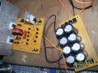
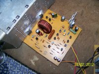
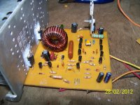
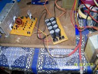
some pics, +/- 65 vdc running smooth, aux transistor need heatsink at this voltage supply, its not needed bigger heatsink at the output transistor, i just mount it for testing at first time. PSU = Harman Kardon big trafo, supply caps 3300uf x 8, supply diode 6A 08 x 8. will take video later while amp playing.
 

Attachments

  • 100_1715.jpg
    100_1715.jpg
    302.2 KB · Views: 344
  • 100_1716.jpg
    100_1716.jpg
    292.7 KB · Views: 240
  • 100_1714.jpg
    100_1714.jpg
    366.5 KB · Views: 292
  • 100_1718.jpg
    100_1718.jpg
    278.1 KB · Views: 262
  • 100_1717.jpg
    100_1717.jpg
    478 KB · Views: 207

norazmi

diysmps Senior Member
Hi Norazmi
greetings just need your help if you can i need your help to stimulate bridged amp using IR2110 74HCOO LM311 schematic looks good only want to confirm it after stimulation in LT SPICE hoping you can help out
warm regards
michelle

Michelle idk if i have 74HCOO, but i`ll try with other way lets see they run in full bridge.
 

norazmi

diysmps Senior Member
at +/- 65 vdc the only heat is filter capacitor, i`ve use 250vdc 470nf, heating about 45c i think, lol, i think its because large current flow through it. Inductor is only warm material iron power T106-2.
 

norazmi

diysmps Senior Member
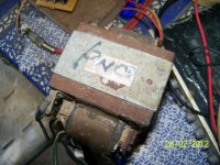
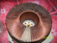
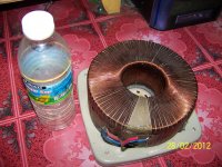
This is my 2KVA trafo, very heavy and primary winding use AWG 18 coil, i`m not finish yet winding at secondary, hehehehe :D
 

Attachments

  • 100_1720.jpg
    100_1720.jpg
    511.1 KB · Views: 184
  • 100_1719.jpg
    100_1719.jpg
    422 KB · Views: 131

stewin

Member
nice work on PCB . why didn't you use double circuit ? i heard in forums double circuits helps in noise reduction, because of grounding plane. do you have noise ? what are the fets used?
 

norazmi

diysmps Senior Member
no noise, more faster mosfet will be less noise, that one irfb33N15D, today i do test with several mosfet, IRF540 Rds-on=0.077 provide noise when u put ur hear at speaker, IRF540N Rds-on=0.04 no noise, IRFP140N Rds-on=0.04 no noise, IRFB4710 Rds-on=0.01 Perfect!! powerfull. IRFP250N provide noise same as IRF540, and others same depend on how fast that mosfet can handle.

Double circuit board will be more small pcd, its good, but i dont like double sided board :D
 

norazmi

diysmps Senior Member
here is the video, no noise, crystal clear sound, good low, mid and high... LOL i think im starting like this amp more compare to Ir2110 ucd version, because of noise IR2110. Idk i need to test more, for the noise is confirm dont have problem. :D

[video=youtube;iW_Y_sPBqA0]http://www.youtube.com/watch?v=iW_Y_sPBqA0[/video]
 

norazmi

diysmps Senior Member
Stewin can u post picture or video with ur ucd discrete, u still have noise problem? For the bass if u got any distort at high volume, i`m asking u to remove 10k resistor at each mosfet, high and low side.
 

norazmi

diysmps Senior Member
Stewin, i know why is 12v zener there, if u refer to original phillips apps note, there is 4.7k resistor from positive rails which on your schematic is 33k, and 4.7k clamp with 12v zener to keep the voltage not over than 12v from positive supply rails. I`ve seen on hypex module similar to this they make separate 12v supply to hi and low side, like we can have aux using tip41c 2 pcs feed on each rails, so we no longer need 33k resistor on ur schema and 4.7k resistor on phillips ucd so we can avoid them both. also 12v zener can be avoid too.

so we have problem if we took 4.7k resistor clamp with 12v zener and by using tip41c to have aux 12v supply, so we have problem here, tip transistor will be blown because of hi current feed through 4.7k resistor, if u remove 12v zener without only, and aux supply at hi side will be more than 12v and will blown mosfet, then u take 33k resistor and i`ve measure that voltage is about 15v is acceptable. But its for max +/- 50vdc, if more than that the 33k resistor need to change or mosfet will blown again.

for my opinion to have enough current and stable at aux supply on each hi and low side we should mount 2 tips or even hinger voltage like MJE13005-007-009 for high voltage so we no longer need to care about 12v zener clamp and resistor change. and seems that this solution to be safe, i do simulation with this configuration and lets see how its going. If success i`ll do it experiment it in real life, because i do simulation with 33k res and without zener 12v is not enough aux supply on hi side, this will provide distort at high volume too.

regards
 
Top