hi nozrami i told you this amp is very powerfull .BTW if you think the power is little just bridge it will drive your load comfortably. thanks thanks for your your simulated schema . I've been testing it today with my smps due to the noise reduction it is loud and very powerfull clear even in the mid section . yes there is small amount of noise if you put your ears very close i.e next to the speakers i'll post pictures as soon as i get a camera . i did as you suggested and put a variable resistor (1k) in series with a 100 ohm resistor if the sum total resistance is 330ohms it works well at low volumes but there is some distortions if driven hard the fets are cool (IRFP250) . but if i set the resistance at 310ohms the fets(IRFP250) warm get hot and require a bigger heatsink but the sound is clear and high fidelity at high output levels . here is the pcb and schema i used. boards sizes are 194.5mm x 49.5mm
Attachments
-
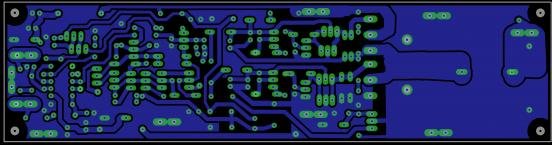 gtG ucd single discreet without protc bd139 bd140pcb bottom.jpg21 KB · Views: 302
 -
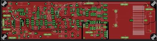 gtG ucd single discreet without protc bd139 bd140 top.jpg20.8 KB · Views: 242
 -
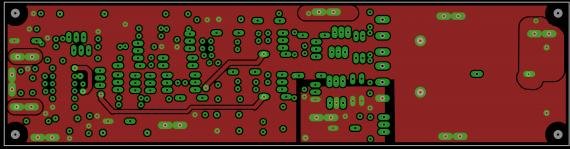
 gtG ucd single discreet without protc bd139 bd140 bottom.jpg20.4 KB · Views: 221
 -
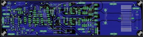
 gtG ucd single discreet without protc bd139 bd140pcb top.jpg21.3 KB · Views: 163
 -
gtG ucd single discreet without protc custom small sink 2 bd139 bd140 schematic.pdf31.4 KB · Views: 639
