You are using an out of date browser. It may not display this or other websites correctly.
You should upgrade or use an alternative browser.
You should upgrade or use an alternative browser.
Another IR2153 smps
- Thread starter borysgo2
- Start date
wally
It works very easy, It uses reactance of the capacitors. The picture bellow shows how it works. I am a bit angry that I have wasted so many time and mosfets trying to get current sense trafo + CT pin combo to work, and after a good few days I have found a solution but it costed me a lot of time and nearly 5-7 pairs of transistors.
Today it took me around 15 min to get it work, no burned mosfets and protection works OK.
Regards
Attachments
-
 capactive current sense.jpg19.7 KB · Views: 87
Last edited:
[video=youtube;xGty-EfOQX4]https://www.youtube.com/watch?v=xGty-EfOQX4&feature=youtu.be[/video]
Simple test how it works. The load is 240W (two bulbs), when the filament is cold they are taking more current so OCP is limiting the current. During startup current is limited too, so OCP is providing soft-start for half bridge part of the converter.
Simple test how it works. The load is 240W (two bulbs), when the filament is cold they are taking more current so OCP is limiting the current. During startup current is limited too, so OCP is providing soft-start for half bridge part of the converter.
Last edited:
I do not know very much about current limit circuits but i know everyone that has tried to make them says it takes a long time and you burn out a lot of switches. I looked at your simulations and several mS seemed like a long time to me for the protection trigger so i googled around and found one document that said you needs 10uS response for igbt's. Top of page 14.
Attachments
Thanks for a document.
Simulation only presents how it is working.
Please take a look at the real animal bellow, the current is limited to the MAX that smps can handle safely (current is not rising above seted value), in my case 70kHz I have 14us in between the cycles so it is impossible to make it work in 10us. If I will reduce filtering cap (I have 470nF right now) a good bit the protection can work really instantly.
I didn't invented it. It is only a small capacitor series with resistor and than the AC component is rectified and filtered, the same as with current sense transformer.
In my case I was doing prapobly something wrong with current sense transformer, I wired it up 1:50 and the measured current ratio was approx 1:33, further problems I had with spikes commig from it, smaller or bigger but allways there, so they need to be filtered out, if I will filter them too much the protection will be too slow and etc.
In my case I was doing prapobly something wrong with current sense transformer, I wired it up 1:50 and the measured current ratio was approx 1:33, further problems I had with spikes commig from it, smaller or bigger but allways there, so they need to be filtered out, if I will filter them too much the protection will be too slow and etc.
Borysgo2
I really like and very much appreciated your application of capacitor divider as a replacement for current sense trafo.
because I have also been thinking that before and now you successfully implement it..For me it's no that easy to make experiment
on things like that especially to a dangerous smps..but I'm happy that you did it and shared it in this forum..
May I request to you to show it again on the modified schematic showing the connection of the capacitor divider as current sense for OCP?
Thanks for your positive response..
Regards,
Demykiko
demykiko
Thanks
The schematic is in post no42. The C1 and R1 are sensing the AC component at the series capacitor at half bridge converter (the two 470nF caps are dynamicly seen as the ~~1uF single capacitor), that voltage is rectified with D1 and D1, R2 is load resistor or potentiometer for trigger level adjustment, voltage on R1 is filtered with small capacitor (bigger the cap = longer delay). V_out is your triggering voltage, some of the controllers use 0,6V level, I have used transistor here to pull down the Vcc , so I need approx 0,6-0,7V base-emmiter voltage to get the protection trigerd.
Soon I will post complete smps project, I have the boards nearly ready.
I have been thinking about this circuit a lot. I think what is going on is you are measuring the ripple voltage increase as the current increases. I do not believe this is a repeatable measurement. The ripple voltage is determined by the bulk input capacitors. As the capacitors age the ripple voltage will change. You may have to re-calibrate your current setting once or twice a year is my best guess. I do like this circuit though it is very clever, good work.
Thanks Borysgo2
I saw the photos you mentioned but it's so small to see all the details..If it's okay to you can you make it big?
also thanks for your further explanation of how it works..
another thing, how did you connect the two series 470nf, are they in parallel with the 1uf cap?
Regards,
Demykiko
I saw the photos you mentioned but it's so small to see all the details..If it's okay to you can you make it big?
also thanks for your further explanation of how it works..
another thing, how did you connect the two series 470nf, are they in parallel with the 1uf cap?
Regards,
Demykiko
Last edited:


Jagd.Panther
New member
I have been thinking about this circuit a lot. I think what is going on is you are measuring the ripple voltage increase as the current increases. I do not believe this is a repeatable measurement. The ripple voltage is determined by the bulk input capacitors. As the capacitors age the ripple voltage will change. You may have to re-calibrate your current setting once or twice a year is my best guess. I do like this circuit though it is very clever, good work.
The ripple is measured on split DC-blocking cap. Low frequency ripple is filtered by an RC-network. Very clever imho.
It wouldn't work for cycle-by-cycle current limiting though.

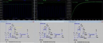
This photo shows the simulation by Multisim and it seems that it proves the split capacitor technique
as an acceptable way for another protection control to IR2153 and possibly to other dedicated IC controllers
The XMM3 tester shows 712 mV or .712 V of the OCP circuit with 5k load..which is enough to trigger the MPSA BJT to shutdown the supply of IR2153
The XMM2 shows that more than 600w of LOAD (in this case it is 166.084 volts/40 ohms is 689.6 watts) the OCP circuit will be activated.
The 5k ohms load resistor of OCP can be variable to set the right threshold for different MAX load power..this time it is set to 600w.
Microsim
The current schematic is in post 52, it is going to change a bit, I will have to finish off new layout.
It will be universal SMPS that you can putt any driver board (ir2153, SG2525,TL494, LLC, etc), it will call i-SMPS.
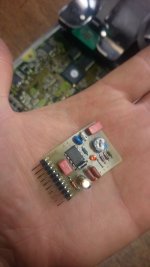
Bellow first driver board with popular ir2153 (UVP,OCP, OTP).

The current schematic is in post 52, it is going to change a bit, I will have to finish off new layout.
It will be universal SMPS that you can putt any driver board (ir2153, SG2525,TL494, LLC, etc), it will call i-SMPS.
Bellow first driver board with popular ir2153 (UVP,OCP, OTP).
Attachments
-
 control board.jpg118.1 KB · Views: 179
Last edited:
Jagd.Panther
New member
Nice board! BTW is that an ECM/ECU on the background?


