You are using an out of date browser. It may not display this or other websites correctly.
You should upgrade or use an alternative browser.
You should upgrade or use an alternative browser.
Class D 200 Wrms with 2 mosfet cheap
- Thread starter norazmi
- Start date
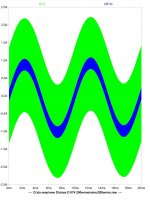
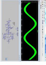
lt spice, i`ll post the thd result later, i need to find it in my external hd, since long time im not continue with this mini amp, i just use this amp for hifi system at home and for high power i`ll go with ir2110 or discrete.
Attachments
allright stewin, i did build this amp again yesterday, i`ll post it here the picture, today im going to finish ir2153 smps with protection too, but this smps is for irs900d with +- 75vdc vout. probably you need to check voltage at tl074 with clamp diode 5.1 and tell me what u get, what material for the core you use, with how many uh, and filter cap at output. i just use flyback trafo ferrite core from old tv which already have an air gap at center and i did 33 uh with 470nf filter cap.
i already test new one with very high volume and i dont have such as probem with rf noise at high or low freq, if you have crossover coil at your speaker, so try dont use it. sometimes damage 5551 and 5401 transistor also give some noise at output, so better check it out. sometimes ppls do mistake by put 12 or 15 v zener diode to supply tl074 will damage that transistor, so its need to be change and change clamp diode to 5.1 v.
i already test new one with very high volume and i dont have such as probem with rf noise at high or low freq, if you have crossover coil at your speaker, so try dont use it. sometimes damage 5551 and 5401 transistor also give some noise at output, so better check it out. sometimes ppls do mistake by put 12 or 15 v zener diode to supply tl074 will damage that transistor, so its need to be change and change clamp diode to 5.1 v.
thanks norazmi again for reply. i use 5v6 for voltage of tl074. my output inductance is about 80uh. t-106 26 with 1mm gap 33turns and 0.47uf at output. when i used less uh like 30uh .that is .t-106 26 with 1mm gap 20turn the outputs were heating even at 8ohms load.
by the way i do not have inductance meter i used mini ring pc software.
by the way i do not have inductance meter i used mini ring pc software.
here is the picture, video will upload within few mins, i made class d 200 wrms and ir2153 with protection, all is new made about 2 days ago. mosfet irf540 and irf9540, inductance 33uh using old tv ferrite trafo with air gap at center and 470n filter cap. smps output +- 48 vdc and i have another trafo with +-74 vdc for irs900d will be test on next week. smps run at 100khz, for user who want try made smps i would like to suggest for first time power up please use series with at least 60w bulb lamp. if smps goes wrong maybe short or not suiteable trafo is being use, lamp will be bright on or lamp will be on and off, mosfet will be warm with that problem. if the smps dont have problem, lamp will be off and smps is running without problem. i`ve on smps and class d amp whole day today to see is there is any problem but all is ok even play hard and voltage drop only 0.5-0.7 v. seems this smps can support for class d 200wrms without problem. Anything you can ask me here 
.


.
glo you are using irf740 and irf9640 for class D? its bad idea because irf740 have high capacitance and you`re incresing the freq also not good, of course it will damage your output mosfet and when this happens it will deliver dc at output speaker, next time use dc protect to make dummy test.
caliber class D ca-8000i.
Today im repair caliber class D amp, this amp is broken because mistake main input connection from 12vdc, my friend just connect this amp from hes HINO which using 24vdc battery and the amp explode into fireworks. I repair this damn thing about 2 days because the whole circuit using protection LM393 and lots of opto too, its simple class D amp with 36.6 vac x 2 run on irfb23n20d i think. for the input buffer they use LM4558 like op amp TL072. i might draw the amp section maybe, but this amp produce little heat while idle without heatsink. dc offset is 0.028. they parallel 4 output mosfet and still half bridge. but i didnt see any filter caps after output inductor or before and they just put 4 pcs 1000uf 100v bipolar caps . some picture below and this amp already finish repair and its working now.
**upload file not working, i`ll upload later.
Today im repair caliber class D amp, this amp is broken because mistake main input connection from 12vdc, my friend just connect this amp from hes HINO which using 24vdc battery and the amp explode into fireworks. I repair this damn thing about 2 days because the whole circuit using protection LM393 and lots of opto too, its simple class D amp with 36.6 vac x 2 run on irfb23n20d i think. for the input buffer they use LM4558 like op amp TL072. i might draw the amp section maybe, but this amp produce little heat while idle without heatsink. dc offset is 0.028. they parallel 4 output mosfet and still half bridge. but i didnt see any filter caps after output inductor or before and they just put 4 pcs 1000uf 100v bipolar caps
. some picture below and this amp already finish repair and its working now. **upload file not working, i`ll upload later.
glo you are using irf740 and irf9640 for class D? its bad idea because irf740 have high capacitance and you`re incresing the freq also not good, of course it will damage your output mosfet and when this happens it will deliver do c at output speaker, next time use dc protect to make dummy test.
norazmi in my setup irf740/9640 better than irf540/9540. but other setup may diferent
Today im repair caliber class D amp, this amp is broken because mistake main input connection from 12vdc, my friend just connect this amp from hes HINO which using 24vdc battery and the amp explode into fireworks. I repair this damn thing about 2 days because the whole circuit using protection LM393 and lots of opto too, its simple class D amp with 36.6 vac x 2 run on irfb23n20d i think. for the input buffer they use LM4558 like op amp TL072. i might draw the amp section maybe, but this amp produce little heat while idle without heatsink. dc offset is 0.028. they parallel 4 output mosfet and still half bridge. but i didnt see any filter caps after output inductor or before and they just put 4 pcs 1000uf 100v bipolar caps
**upload file not working, i`ll upload later.
What is the problem into uploading files?


11robizver11
New member
Hi
I have made this amp with this pcb ( http://www.diysmps.com/forums/attachment.php?attachmentid=1820&d=1325111792 )
I have problem with output dc voltage.On output i get 46v
Output mosfets : IRF9540 and IRF540
+-50v supply
please help me
sorry for bad english!!
I have made this amp with this pcb ( http://www.diysmps.com/forums/attachment.php?attachmentid=1820&d=1325111792 )
I have problem with output dc voltage.On output i get 46v
Output mosfets : IRF9540 and IRF540
+-50v supply
please help me
sorry for bad english!!
finish the amp and smps, will post picture or even video tonite, tested today all work great
Hello Norazmi.
I have just read through the whole thread. Interesting reading, indeed!
You're doing a great job here. Keep up the good work!
I'm just curious about the smps you are using here. Do you have any information about that?
I'm interested in building an class D amp for a home theatre subwoofer and of course I also need a power supply.
This combo of yours sounds very interesting. This would also be my first built amp, although I'm not new to electronics...
Regards,
Leif