Drive signal issues with half bridge

I've been investigating on the inductance side and back calculating AL cores, for the CFL toroids they range from 5000 to more than 12000 the on am using is at 7346. However between calculating turns and inductance and winding and measuring inductance there is a difference, more turns have to be added in practice.


For the EI33 core it has an AL of 861 but i have an cleaned ETD34 handy that has an AL of 3885 I will give that core a try.

According to calculations and assuming i would have needed an inductance of 2.2mH on my main core, i would need 50 turns instead of 40. With 40 turns i have an inductance of 1.5mH. I will unwind and rebuild that transformer. Can anybody comment on this thanks
 

Yosemite

New member
I've been investigating on the inductance side and back calculating AL cores, for the CFL toroids they range from 5000 to more than 12000 the on am using is at 7346. However between calculating turns and inductance and winding and measuring inductance there is a difference, more turns have to be added in practice.


For the EI33 core it has an AL of 861 but i have an cleaned ETD34 handy that has an AL of 3885 I will give that core a try.

According to calculations and assuming i would have needed an inductance of 2.2mH on my main core, i would need 50 turns instead of 40. With 40 turns i have an inductance of 1.5mH. I will unwind and rebuild that transformer. Can anybody comment on this thanks


That means EI33 will saturate very fast making your Switching devices to blow at small load, 100W or so, I dont like that core.

ETD34 will give your at least 500W at let say 70KHz. calculated at Bmax of 1200.

Primary inductance is not a big problem, as your core saturates fast with AL of 861, very low
 
Hi Yosemite thanks a lot for the reply. I do understand your point. I will wind a new transformer with the ETD34 core that i have handy. I will try to aim for 250W output power on the prototype that am making and around 400W for final unit using ETD44 cores i jut purchased. 70Khz and Bmax of 1200 is not a bad idea that means less turns i will try to implement it.
 
I have Calculated the number of turns for the ETD34 i got for 160V Area of 0.95cmSQ 70Khz switching freq and Bmax of 1200G I get 50 turns primary and 11 turns secondary. I have also rewound my gate drive transfo on a higher al core of 9000 for around 3X30 turns trifilar its measuring 2.5mH. The current sense transo has also been rewound for 1:60 turns. I will implement these measure the waveforms at 12Vac and post back.
 
New Magnetics and test results

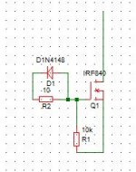
Hi I've changed the core to ETD34 50 turns primary and 2X11 turns secondary. The GDT transfo has been changed to a core of AL 9000 and a current sense implemented for measurement only with 1:70 turns and loaded with 470 ohm as in the schematic:Schematic.jpg

Tested at 12Vac all ok. The attachement shows test results at 40Vac and 1K load on each output and then 40Vac input and 47Ohm load on each output:New Test.jpg

Please comment if you see anything wrong with the waves. Thanks
 

MicrosiM

Administrator
Staff member
Hi I've changed the core to ETD34 50 turns primary and 2X11 turns secondary. The GDT transfo has been changed to a core of AL 9000 and a current sense implemented for measurement only with 1:70 turns and loaded with 470 ohm as in the schematic:View attachment 1161

Tested at 12Vac all ok. The attachement shows test results at 40Vac and 1K load on each output and then 40Vac input and 47Ohm load on each output:View attachment 1162

Please comment if you see anything wrong with the waves. Thanks


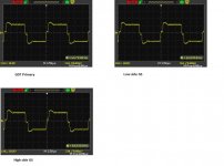
All waves are OK, except the GS ones . I gave you a circuit long time ago, follow it.

can you measure voltage of that wave GS of Mosfet using oscilloscope?

This wave wont turn ON/OFF Mosfet properly.


I will show you proper wave Across GS
 
Hi Microsim, i know the shape of the wave its a positive square wave with a crest just after the rise time and it falls remains steady and has a sharp fall time. My GS waves looked exactly like that before i changed the GDT core from an EEL16 with AL800 to the actual 1cm toroid one with an AL of 9000 and the mosfet gate drive scheme. I will try a simplified gate drive sheme similar to the one you sent in the schematic with SG3525 with only 4.7R gate resistor. If it does not work i will go for this one:Capture.JPG which you have used in your IR2153 SMPS.

I feel it could be the gate drive circuit which is shaping the wave to look completely square.
 
Last edited:

MicrosiM

Administrator
Staff member
Wave

Hi Microsim, i know the shape of the wave its a positive square wave with a crest just after the rise time and it falls remains steady and has a sharp fall time. My GS waves looked exactly like that before i changed the GDT core from an EEL16 with AL800 to the actual 1cm toroid one with an AL of 9000 and the mosfet gate drive scheme. I will try a simplified gate drive sheme similar to the one you sent in the schematic with SG3525 with only 4.7R gate resistor. If it does not work i will go for this one:View attachment 1163 which you have used in your IR2153 SMPS.

I feel it could be the gate drive circuit which is shaping the wave to look completely square.

I think that too
 
Amended Gate drive

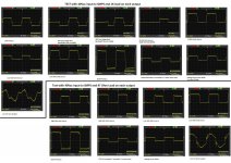
Hi Mirosim i have simplified my gate drive to this: Latest Schematic.JPG and these are the new waveforms:corrected waveforms.jpg. The waves were captured with 12Vac applied to the smps and 47ohm load on each output. I will wait for your reply before proceeding to test with 40Vac
 
Test with 40Vac

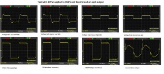
Hi Microsim please find atatched the test with 40Vac and 47 load on each output LAtest test.jpg. There is a small spike appearing on the transfromer secondary. Please comment i will wait for your reply. Next step is test with 109Vac
 
Hi microsim the psu passed the 109Vac test nothing heating and its giving +-13.8V on output loaded with 100w lamps.Mosfet and heatsink are cold. What would you advise as next step? No snubbers implemented yet.
 

MicrosiM

Administrator
Staff member
Hi microsim the psu passed the 109Vac test nothing heating and its giving +-13.8V on output loaded with 100w lamps.Mosfet and heatsink are cold. What would you advise as next step? No snubbers implemented yet.


Do one thing

Use Voltage doubler, and Dont load it at first, keep it connected for a while, check heat.

If things are OK, load it 100W, and check WAVES. are you isolating your oscilloscope from mains?

Check GS waves. DS waves specially
 
Hi Microsim thansk for the reply, i can do that. My scope is always grounded and my PSU is isolated from mains by my two transformers i prefer it that way and probes are connected with the system off to avoid electric shocks.

I will connect a 1K load and run it at 210Vac and measure the waves and the same thing loaded with my 100W bulbs
 
Hi Microsim bad news the mosfet blew but the supply kept running with +-28V on output for something like 30 mins or so. It was fed with 210Vac from my transformers and loaded with 1K load on each output. The mosfet did not heat up but the core was getting warm. I will replace the dead mosfet. I think it could be the leakage inductance of the core or spikes that appear on the core primary at high voltage that killed the mosfet. I will redo the test and check for spikes at 109Vac
 
Last edited:

MicrosiM

Administrator
Staff member
Hi Microsim bad news the mosfet blew but the supply kept running with +-28V on output for something like 30 mins or so. It was fed with 210Vac from my transformers and loaded with 1K load on each output. The mosfet did not heat up but the core was getting warm. I will replace the dead mosfet. I think it could be the leakage inductance of the core or spikes that appear on the core primary at high voltage that killed the mosfet. I will redo the test and check for spikes at 109Vac

Thats good thing, 30 minutes without heat of Mosfets, means the start of success

i cant tel the exact reason for mosfet blowing, I told you to check waves at every stage. and you didnt. :"::

show some new close pictures of the SMPS
 
Hi Microsim i do understand your point but given the price i paid to get a scope for my location, i prefer to let it run first to see if it survives long enough and then connect my scope to it. Since i know the issue is at 210Vac i will replace the mosfet and test it at 109Vac to check for any issues. Do you mean you want a picture of how the components are laid on the board? If yes i can take a picture and post it here
 
Top