You are using an out of date browser. It may not display this or other websites correctly.
You should upgrade or use an alternative browser.
You should upgrade or use an alternative browser.
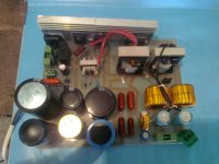
Easy SMPS for everyone :)
- Thread starter Acca
- Start date
acca i have some good newsssss....
it's workingggg.... :w) :02.47-tranquillity:
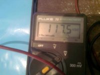
i have 52 volt with no load at the outpout...
when i conect a 6 amps load i drops to 45 volt....
i pushed it hard to 8 amps and voltage drops at 38 volts..
i'm using ei33 transormer with 40 turns primary...
at the feedback i use 39 ohm 5 watt resistor...
what can i do in order too have smaler voltage drop?
maybe increase frequency?
it's workingggg.... :w)
i have 52 volt with no load at the outpout...
when i conect a 6 amps load i drops to 45 volt....
i pushed it hard to 8 amps and voltage drops at 38 volts..
i'm using ei33 transormer with 40 turns primary...
at the feedback i use 39 ohm 5 watt resistor...
what can i do in order too have smaler voltage drop?
maybe increase frequency?
acca i have some good newsssss....
it's workingggg.... :w):02.47-tranquillity:
i have 52 volt with no load at the outpout...
when i conect a 6 amps load i drops to 45 volt....
i pushed it hard to 8 amps and voltage drops at 38 volts..
i'm using ei33 transormer with 40 turns primary...
at the feedback i use 39 ohm 5 watt resistor...
what can i do in order too have smaler voltage drop?
maybe increase frequency?
Increasing the frequency will never make the voltage increase, or lowers the voltage drop.
Ive done many tests trying to prove the calculations formulas, and relation of voltage increase, none shown true results.
The only way that frequency will affect the SMPS, is it will help you to use a small inductor
Thats all
i was thinking that if i increase frequence ei33 will outpout more watts(around 300 watt at 40-50 khz)so i would have less voltage drop...
i will use a pair of ei33 tansformers with the primaries in parallel and the secondaries at series..
so i will have 2x60 volts and 5 amps rms at each rail...
and some more amps peak....
is this enough for 2x300 class d amp?
i will use a pair of ei33 tansformers with the primaries in parallel and the secondaries at series..
so i will have 2x60 volts and 5 amps rms at each rail...
and some more amps peak....
is this enough for 2x300 class d amp?
i was thinking that if i increase frequence ei33 will outpout more watts(around 300 watt at 40-50 khz)so i would have less voltage drop...
i will use a pair of ei33 tansformers with the primaries in parallel and the secondaries at series..
so i will have 2x60 volts and 5 amps rms at each rail...
and some more amps peak....
is this enough for 2x300 class d amp?
I forgot to mention that you can extract more power from any core at higher frequency, if that core can run at the higher frequency
i know that...
winding at my transfomrer is for 300 watt..
now at this low frequency it outpout about 250 watt..and maybe less...
thats whay i said to increase the frequency...
the transformer will oupout 300 watt and i will have less voltage drop....
that's what i was thinking....
i can't take more than 500-600 watts with my transistors..
i use mje13009....
hi guys..
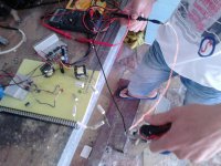
i made the smps and it's working fine...
i used 5 turns primary at the bdt(core from cfl lamp) and 22ohm feedback resistor and voltage drop improved for 5 volts comparing to 8 turns primary and 47 ohm resistor...
i used 48 turns primary at erl35 instead of 40 turns...
with 40 turns the core is saturating because the frequency is too low...
i pushed smps to 385 watts with erl35 and mje13007 and it worked fine...
i have 12 volt voltage drop at 385 watts with only 400 μf bulc capacitor..
if bulk capacitor increase voltage drop will decrease....
Sir,your transformer is like original 
I will post my uSMPS tonight,with original E19 from atx (no rewounding) that power 12V 45W light bulb
I use 13003 transistors and 100nF primary cap's (that go to transformer).
Bulk cap 33uF,Instead NTC and fuse I use 4R7 1W
No storage inductors (because core is gapped)
Output voltage with original windings is 10V,17V and 27V (depends where you attach output rectifier).
Micro SMPS
Really micro SMPS
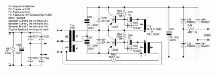
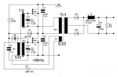
Schematic same as on first page
My version use:
Transistors: 13003,no heatsinks
Bias Resistors: 680k
Divider capacitors: 47nF 250VDC (I plan to use 100nF)
Feedback resistor: 100R 0,5W
Bulk cap: 33uF 400V
Output cap: 470uF 25V
Input is rectified with only one diode,and 4R7 1W is used as softstart and fuse
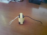
Core:E19 from PC PSU,not rewounded,Primary used as primary and 5Vstandby secondary is used for feedback.It outputs about 10V when rectified.Other posibilities are 17 and 27V (depend where you tie output rectifier)
Rectifier is classic diode bridge with 4 fast diodes.
No output storage coil because core is gapped.
Ideal for AUX power supplies,LED power supply,Power SMPS supply for oscilator and drivers,amplifiers,etc.
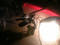
On other prototype I use pins of secodary that give me about 17V,and then use 7812 stabiliser.Output current drawed from this secondary (without 7812) is about 4A for 1 minute,I use 12V 45W light bulb,and they shine very bright,like to blow up
On 10V secondary it can shine continually without any problem.
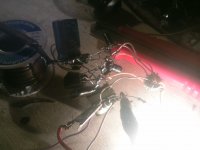
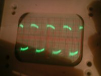
Scope shows output voltage at GND and 5V pin.
See pictures:


Last edited:

