Problem with IR2153 SMPS

MyFirstSMPS

New member
Hello all!

I am writing my first post in this forum. I am very pleased it this forum exists. I must first apologize my bad English - I try to study independently but technically is difficult.

But, go to the point, precisely the problem.
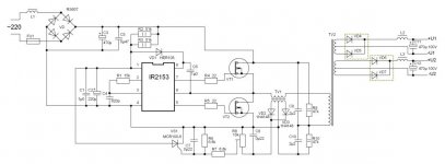
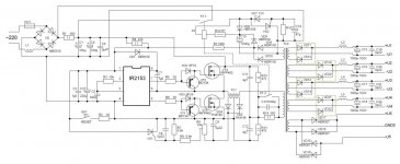
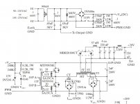
I have now built three SMPS and 2 of them are working nicely at the moment, they are working 12 Vdc supply voltage. Finally, the third works for mains voltage ~230 V, and is based on the popular IR2153 driver, Half-bridge configuration, using the IRF740 power MOSFETs. Ferrite toroid power transformer TV2 are made, as the same as N27 material but Russian substitute, M2000NM ferrite. The core size is 45*28*24mm (O*I*h). The primary consists of 4×0.4 mm wire, 55 turns, SMPS also exists ferrite toroid current transformer TV1, the same material with dimensions 20*12*6. The current transformer primary winding is 4*0.4 mm wire, 3 turns. Secondary consists of 2*3 turns (two wire-wound at the same time), then connected in series, to achieve symmetry.

R8 regulated overload protection in place
Question - what would be the optimal resistance which it started?
My test SMPS use C5 1uF capacitor, C3 is 470uF/450V.
R2 and R3 is 56 k-ohm/2W
R4 and R5 is my test 27ohm
R9 and R10 are in 56k-ohm /2W

I am powered up this SMPS first test through the isolating transformer in addition to the filament bulb, all worked fine, nothing to excess heat. If, however, does last attempt to connect the outputs in series, the main fuse was burned:"::, all the connections to the transformer according to the correct, or should make dual polarity, connecting otherwise?

At first, everything was working nicely, regulation of SMPS input of about ~210V, and then burned to the fuse of excess flames or smoke are not generated. After the power is turned off the transformer was warmed for about 60 to 70 degrees - is possible, incorrectly connected the windings?
However, the voltage at the load (incandescent bulb) was same than double the individual windings.
Replacing the fuse and starting the voltage of about ~120V but fuse was burned again, so I must check the MOSFET and IR2153 but they probably have now been destroyed?

Maybe the experts are able to responding my question - if this circuit

is at all worth the effort or should try something else?
Please follow the recommendations that I am still a newbie at the SMPS, and initially very complex circuits would not want to try.

Scares me a bit of the transformer winding, the SMPS is different from the iron core winding technology and I have a negative experience ETD34 winding. For winding a toroid, in all cases I have gained symmetry.

I have a storage oscilloscope, measuring equipment, both analogue and digital multimeters, auto-transformer 2.5 kVA, isolation transformer 2kVA. At the moment there is not yet LCR meter, however, I try to get it.


Yours sincerely
 

Attachments

  • SMPS IR2153 400VA.jpg
    SMPS IR2153 400VA.jpg
    47.3 KB · Views: 689

MyFirstSMPS

New member
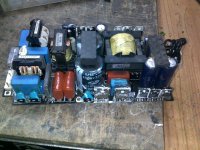
I post my SMPS a few photos, maybe someone can help the problem, described in the first post.
By reading the forum, I continue to believe the IR2153 is good and would like to get it for a functioning power supply.
By reading the thread: http://www.diysmps.com/forums/showthread.php?79-1kW-smps-project-(based-on-Micros-Design)/page17 also got a good hint of how the ETD core windings wrapped CORRECTLY. Thanks to MicrosiM!
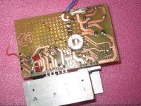
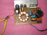
I'll add pictures from my power supply top view and PCB bottom tracks, which is this moment also located the current transformer and fuse.
 

Attachments

  • SMPS IR2153 current.jpg
    SMPS IR2153 current.jpg
    391.2 KB · Views: 246
  • SMPS IR2153 place.jpg
    SMPS IR2153 place.jpg
    476.8 KB · Views: 539
Last edited:

wally7856

New member
How many watts are you trying to make?
What frequency are you running?
What is the Ae (cross sectional area) of the toroid.

C9 and C10 are 2.2uF. All of the current to the transformer must pass thru them. I would think both of these capacitors have burnt up. You need much larger capacitors here. They should be at least as large as C3.
 

MyFirstSMPS

New member
Hello wally and others.

Power should in this circuit, somewhere 400 to 600W.
I would like to keep the initial frequency of 60 to 70kHz to determine temperature raise of the transformer, if does not rise very much, I would like to increase the frequency of about 100kHz. This ferrite should be used at 100kHz (similar to the N27).
Core cross section, and other indicators - below.


C9 and C10, have the K73-17 capacitors. These are Polyethylene-Terephtalate (PETP) capacitors, operating voltage at 250Vac. These are fairly robust design and used a sharp charge-discharge circuits. Realistically, they can tolerate a much higher voltage, the picture they see is the blue "pillow" next to the input filter. C3 is paralleled Vishay type MKT368 0,47uF/400V (at the moment instead of 2.2 uF).
An electrolyte capacitor C3 is 470uF/400V.
In this case C9 and C10 should be extremely large :D.
Also, I have not seen such circuits - the refurbished inverter welding machines do not come across such a large Film-capacitors. These capacitors not have so colossal, good to their level is 0.5 to 1% of the input filter debugging capacitor. However, on the edge steepness of these capacitors must be a very good, thousands, even tens of thousands of volts per microsecond. They must be able to pass through the short term to have a very high-energy pulses. They must also be kept to a low loss factor.

I looked circuit, and apparently I am wrong Ct and Rt frequency determining circuit selection - Rt is 15 kilo-ohms and Ct is 820pF, it does not match while the transformer is calculated to operate at a frequency of approximately 60kHz

The transformer has a following properties:

Core cross section Ae= 204mm2
Initial permeability Al=1700-1800
Value of induction saturation (0.4 T) typically 380mT
Effective magnetic length Ie=114,5mm
Effective volume Ve [mm3] =23380mm3


However, this configuration worked but the output connected in series killed the IR2153 and IRF740.
I´m getting new parts in Monday.
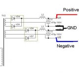
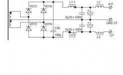
I doubt whether such a connection at all is right - to connect to both outputs like attachment "IR2153 output" or as shown "IR2153 output corrected" ?

I connected to the first, and then heat up the transformer :"::
 

Attachments

  • IR2153 output.JPG
    IR2153 output.JPG
    15.4 KB · Views: 274
  • IR2153 output corrected.JPG
    IR2153 output corrected.JPG
    13.1 KB · Views: 247
Last edited:

wally7856

New member
This is what i see so far.

1 - Change C9 and C10 to 470uF or larger capacitors.

2 - Consider using one of the old C9 or C10 capacitors in series with the transformer primary. This helps prevent flux walking or stair-casing.

3 - Your switching frequency is currently at 58Khz with R1, 15K and C4, 820pF. Your transformer primary has 55 turns, this is to many turns for this frequency. Change your switching frequency to 27Khz. This will let you operate at .140 T flux and you can keep the 55 turns.

The picture is one i found on this forum showing the capacitors we talked about.
 

Attachments

  • ir2153 300wattsmps aw91.jpg
    ir2153 300wattsmps aw91.jpg
    26.3 KB · Views: 403

MyFirstSMPS

New member
OK, thank you.
I start from the beginning :)
This circuit I posted is crap...
I did it the second version of this, PCB has already done :"::
All these circuits IR2153 which I have had a similar structure ::SD

Examining the 300W version it appears to be simpler, need to test it:UP:.
Maybe a 500-600VA really much want to start DIY with SMPS.
 

Attachments

  • SMPS 800VA IR2153.jpg
    SMPS 800VA IR2153.jpg
    87.8 KB · Views: 476

MicrosiM

Administrator
Staff member
OK, thank you.
I start from the beginning :)
This circuit I posted is crap...
I did it the second version of this, PCB has already done :"::
All these circuits IR2153 which I have had a similar structure

Examining the 300W version it appears to be simpler, need to test it:UP:.
Maybe a 500-600VA really much want to start DIY with SMPS.

That schematic looks just fine to me, specially the series resistor (R14) witch is a critical part into this design indeed, as without it , it will be impossible to make a current sense method using Current Sense transformer as shown.

Only problem with IR2153D is there is NO softstart circuit inside it, and that makes protection circuit trigger, If you make this design working it will be amazing thing, and will be very good indeed.


Take a look at this poor commercial SMPS, just got 4 of them blown, using IR2153 + IR1150 PFC driver chip, very stupid design in my mind.


IR2153D is good chip for SMPS, but it needs the proper design to make it working, and the design you are showing is just one of the best designs I have seen.

Let us know if you need more help ;)
 

Attachments

  • 19122010328.jpg
    19122010328.jpg
    328.9 KB · Views: 397

wally7856

New member
1 - C11 and C12 are now 4u7 = 4.7uF you need 470uF. These capacitors form a voltage divider. The voltage must hold steady at full loads. You need LARGE capacitors for this. uF = micro farad 10 to -6.

2 - C13 is 1000p = 1000pF= 1nF you need 1uF to 2.2uF high power film capacitor. pF = pico farad 10 to -12 and nF = nano farad 10 to -9 and uF = micro farad 10 to -6.

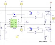
3 - Why did you get so complicated with the FET gate drive. The ir2153 can drive it directly with a low ohm resistor 4.7 ohm or so. Look at JPG for gate drive circuit from ir. Most people only use low ohm resistor. On JPG DNP means Do Not Populate.

4 - There is no reason to have K1 across C13

5 - There is no reason to have R14

6 - R1 should be more like 10 ohm not 360 ohm and 5 watt minimum.

7 - C2 = 1U0 = 1uF it should be .1uF = 100nF = .0000001 farad.

8 - C1 and C4 are not needed if you use the proper size caps for C11 and C12.
 

Attachments

  • gate drive circuit from ir .JPG
    gate drive circuit from ir .JPG
    52 KB · Views: 407

MyFirstSMPS

New member
IR2153D is good chip for SMPS, but it needs the proper design to make it working, and the design you are showing is just one of the best designs I have seen.

Let us know if you need more help ;)

The biggest thanks!!!
OK, it gives me the strength to pass to test -)

I have no problem power transformer re-winding - I have 4 to 5 similar spare ferrite toroid. Therefore, the frequency of the IR2153 was initially not going to change - I can wrap the new, better transformer.
I find various sizes of wires, there is no problem with it. I think that would be better to create more subtle windings, such as 0.2 or 0.31 mm wire - easier to wrap and skin-Efect perhaps better in optimized? HM.. -to work out a little bit of literature -).
R14 I think it that will be okay but - still needs to think about.
Posted first schematic actually works but I'm sure that there is something wrong order of connecting the windings - two independent outputs were working properly, even if accidentally ran into 245V power supply input. Maybe even more than half an hour I have all worked OK. Furthermore, the transformer windings connected in series heat up and main fuse burned out after a minute, quiet pop and that was it - IR2153 and IRF740 couple went quietly - as a Christmas night :D

OK, now I can look forward to Monday when arrive the new IR2153.

Edit: wally sorry, but look Yamaha EMX5000 SMPS - this large electrolyte capacitors MUST BE to be there.
I plan to use this SMPS to powered PA amplifier

The IR2153 output current is too weak to be able to firmly feed the MOSFETs, especially if expected more than 400 to 500VA. It is a complex thing, much determined by the MOSFET characteristic, such as input and output capacitance, the energy to operate properly and much more - It is difficult, but I've only just begun, for example, the Audio-amplifier this is also a determining and I've been doing amplifiers many years.
 
Last edited:

wally7856

New member
I have been looking at power supply schematics and i found an example were the 2 + 2uF split capacitor was used, in a book by Marty Brown. I am very surprised that the low uF can hold up the voltage but apparently it can.
 

Attachments

  • split capacitor 2 = 2 uF.JPG
    split capacitor 2 = 2 uF.JPG
    116.9 KB · Views: 369

MyFirstSMPS

New member
You will not be surprised if collating the electrolytic capacitor and the film capacitor. In vain does not require that the capacitors in the circuit must be very fast charging - discharging cycle. They should be able to charging much faster than the large input electrolytic filter capacitor.
For example, WIMA capacitor FKP1 is a good choice. Also can much better substitutes, such as the MIL-standards.
It's darn difficult to explain this theory.
Since I have not the only day to study English in school when I do learn as himself, and it's damn hard to be understood as complex technical terms and try to figure out how everything works. There are many good books that contain very much.
Unfortunately, such literature is not my native language and I have to look for solutions with multiple languages.
In my concern was thinking that's easier to go here - to get a little advice, and tested on, to get experiences, and get the strength to continue -simple, learn, if necessary, own mistakes.
Keith H. Billings "Switchmode Power Supply", for example - good book, contains a good theory but for a beginner to understand the somewhat complex
 

MyFirstSMPS

New member
I got the new components, and finally an opportunity to measure the inductance of the transformer. I read the book and did some calculations. I drew up power transformer really, really wrong primary data. On the basis of this information is then my original transformer is expected to operate at a frequency of 13.1 kHz :D which is quite ancient frequency in SMPS.
Modeling of the transformer in ExcellentIT calculator, and got very close some of the parameters that I measured in real life.
My real life example, I measured the transformer primary inductances 12.55 mH, the secondary all 4 windings 3,2mH each.
However, complex calculations on the basis of my book gives me the same core, only 23 turns required when the power supply running at a frequency of 60kHz.
Very close data give me the ExcellentIT, I believe that must follow them.
Also, by reading the number of descriptions what in tried and tested in real life, I am of the opinion that the current transformer secondary winding must contain much more turns.
My initial current transformer is a mess.
Books provide current transformer general relations the number of secondary turns 1:100 to 1:200. But I do not have in literature in IR2153 circuits, and it is not, after all, quite a PWM driver, such as the TL494 and SG series.
Since I have no data on the use of the current transformer in IR2153 circuits, I just will need to be tested it.
I still have not come across the basic parameters of the current transformer just use it IR2153.
Is it somehow could be calculated - as a power supply transformer windings passes the current, wrapped new current transformer example primary winding 1 turn and say, for example, 2*25 turns secondary windings.
How do I then get to calculate applied protection current - if the data collated in the thyristor datasheet it expected to achieve a situation where the protection applied to just the right time.

Here I think - most likely I have to buy a bunch of switching transistors, IR2153 and then need test it :D:D
 

wally7856

New member
I still calculate 27Khz for the switching frequency. At this frequency you can get a theoretical power out of 400 watts.

Vpri nominal, 170vdc, you can not move this number around to much. Your line voltage is fixed.
Freq 27,000hz, this is what the other numbers calculate out as.
Flux, this is set by the number of turns. You are at .14T.
Ae, Your toroid is rated at 2.04cm2
55 pri turns, this is what you have now.

If you run the toroid at 60Khz and .1T, I calculate 34.7 primary turns.

A current transformer is not dependant on the chip it is used with. And yes 100 turns is typical.
 

MyFirstSMPS

New member
Yes I've done the calculation error, the 23 turns do not match. I made a new calculation of the IR2153 current frequency - 58kHz. I got a 0.1 T for the required number of 34 turns in reality.
I will prepare a new transformer with the new data by computing. Primary winding wire of 0.5 mm, and I calculated that it needs to be 4 wire. I use double-lacquer coating heat-resistant copper wire which allows operating temperature in 180 degree of Celsius. Secondary side, an initial look forward to +-60V, and I found the calculation of 2 * 16 turns is needed. Initially, using a Ultra-fast secondary side rectifiers, creating a bridge rectifier and the secondary windings in accordance with the immediate connection to the bridge that is needed - no two independent output in this time;).

Inspecting the old transformer I discovered that one of the primary wire insulation affected by exposure to the transformer core, and this was also the electric arc trail::SD.
Core edges are sharp and the wire insulation was damaged from contact with herein.

Also discovered that the seller has given me IR2153 instead IR21531. According to the datasheet is identical but IR21531 has a shorter deadtime - 0.6us.
Can I use IR21531 the scheme without making any changes?
In the new testing I use the IR740 transistors.
 

wally7856

New member
Primary wire size.

.5mm = 987CM / 500CM/A = 1.974A x 4 strands = 7.896A
.5mm = 987CM / 350CM/A = 2.82A x 4 strands = 11.28A

Skin depth at 58khz at 70 Deg C = .3mm

Your primary wire size looks ok.

Toroid, 20mm OD, 12mm ID, 16mm Thick

circumference of a circle = pi x diameter
3.14 x 12mm = 37.68mm

.5mm x 4 strands x 34 turns = 68mm

68mm / 37.68mm = 1.8 layers need 2 layers

34 primary turns / 2 = 17turns per layer

Primary = 17 + 17 turns. With secondary wound in the middle.


58Khz
.1T = 1000 Gauss
Ae, 2.04cm2
170vdc nom, 150VDC low.
34 pri turns


This is what i calculate for your secondary, if i made a mistake hopefully someone will say something.

For +-60 volt output using a center tapped transformer and a bridge rectifier.

60vdc x .707 = 42.42 + 1.4v diode drops = 44vac, for full winding.
You need a 22 volt, 0 volt, 22 volt, winding.

Ns60 = Np 34 x Vsec minV 44 / Vprim min 150V = 9.97 = 10 turns full secondary = 5+5,
5, center tap, 5.

The maximum theoretical output of your toroid at 58Khz is 650W.

650W maximum from core x .7% efficent = 455W maximum music power.

455w / 50 volt DC with head room. = 9.1A x 1.2 for diode configuration = 10.92A secondary current.

The high current secondary will be much harder to wind. Can you buy .6mm wire (skin depth .3mm x 2 = .6mm) .

The following is my best guess from reading books.

.6mm Wire / 25.4 = .02362 = 510CM

510CM / 350CM/A (Hot design) = 1.457A

10.92A secondary current. / 1.457A per .6mm wire = 7.49 strands of .6mm wire. Use 8.

8 strands x .6mm x 10 turns = 48mm

37.68mm circumference of ID toroid. Not enough room.

37.68mm circumference / .6mm wire = 62.8 = about 60 with insulation. / 10 turns = 6 strands per turn.

1.457A per strand x 6 strands = 8.742A max on secondary x .833 diode current multiplier = 7.285ADC

7.285ADC x 50VDC with headroom (ripple 10 to 15%) = 364W maximum music power at 350CM/A. But with very short duration music can probably reach theoretical maximum of 455W.


Differences in IR2153 chips

http://www.irf.com/technical-info/appnotes/an-1085.pdf

“Core edges are sharp and the wire insulation was damaged from contact with herein.”
Smooth the toroid with sandpaper and coat with polyurethane paint.
 

MyFirstSMPS

New member
If i made a mistake hopefully someone will say something.

Toroid, 20mm OD, 12mm ID, 16mm Thick

This is current transformer toroid, 20*12*6mm OD*ID*h.
Power transformer toroid is 45*28*24mm (OD*ID*h).
Is it better to do primary winding in dual layer? Half-primary, then secondary and then half-primary?
Why not full primary in single layer and then against the secondary? Is it bad solution? Too large inductance?


Thanks, I use IR21531D
 

wally7856

New member
“Power transformer toroid is 45*28*24mm (OD*ID*h).”

That is a nice big one, you can get lots of power out of it, at least thousands of watts. But need Ae to figure out how much.

“Why not full primary in single layer and then against the secondary? Is it bad solution? Too large inductance?”

If the primary and secondary are both single layers then one primary and one secondary should be ok.

Do not forget, the turns calculations i did for the primary and secondary was for the old transformer. For new calculations i would need the Ae and the ferrite type.
 
Last edited:

MyFirstSMPS

New member
“Power transformer toroid is 45*28*24mm (OD*ID*h).”

That is a nice big one, you can get lots of power out of it, at least thousands of watts.

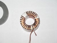
I got today finally made a new transformer.
Below the picture, the picture show only the transformer primary windings.
Primary winding is made 4*0,5mm copper wire, secondary 4*0,71mm.
Also,I let the measurements be the ferrite cores which I have and have some technical data:
Exact permeability - u=1857.
Magnetic saturation was measured - 0.288 T
I calculate the basis of their number, theoretical capacity, and got a surprisingly large value.
However this time the transformer can not be close to the theoretical, I'm waiting for an initial maximum still of 600VA.
Insulation in this time has stronger, I use Teflon.

I made haste previous experiments, using IR2153D, which has already built in bootstrap diode. I hastily added the scheme diode, HER108. As already mentioned, I wrote previously - my scheme worked but maybe someone here can answer a question:
Does the internal bootstrap diode IR2153(D) and IR21531(D) have been mistakenly attached an external diode is bad phenomenon?
 

Attachments

  • new power trans.jpg
    new power trans.jpg
    119.1 KB · Views: 88
Last edited:
Top