MyFirstSMPS
New member
Hello all!
I am writing my first post in this forum. I am very pleased it this forum exists. I must first apologize my bad English - I try to study independently but technically is difficult.
But, go to the point, precisely the problem.
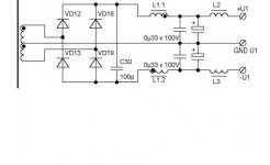
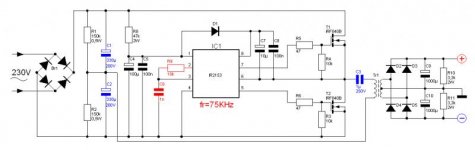
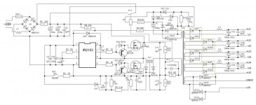
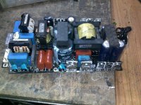
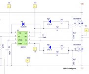
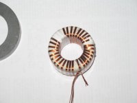
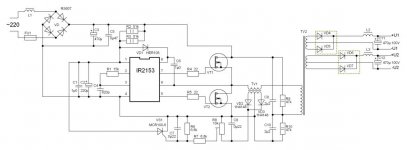
I have now built three SMPS and 2 of them are working nicely at the moment, they are working 12 Vdc supply voltage. Finally, the third works for mains voltage ~230 V, and is based on the popular IR2153 driver, Half-bridge configuration, using the IRF740 power MOSFETs. Ferrite toroid power transformer TV2 are made, as the same as N27 material but Russian substitute, M2000NM ferrite. The core size is 45*28*24mm (O*I*h). The primary consists of 4×0.4 mm wire, 55 turns, SMPS also exists ferrite toroid current transformer TV1, the same material with dimensions 20*12*6. The current transformer primary winding is 4*0.4 mm wire, 3 turns. Secondary consists of 2*3 turns (two wire-wound at the same time), then connected in series, to achieve symmetry.
R8 regulated overload protection in place
Question - what would be the optimal resistance which it started?
My test SMPS use C5 1uF capacitor, C3 is 470uF/450V.
R2 and R3 is 56 k-ohm/2W
R4 and R5 is my test 27ohm
R9 and R10 are in 56k-ohm /2W
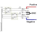
I am powered up this SMPS first test through the isolating transformer in addition to the filament bulb, all worked fine, nothing to excess heat. If, however, does last attempt to connect the outputs in series, the main fuse was burned:"::, all the connections to the transformer according to the correct, or should make dual polarity, connecting otherwise?
At first, everything was working nicely, regulation of SMPS input of about ~210V, and then burned to the fuse of excess flames or smoke are not generated. After the power is turned off the transformer was warmed for about 60 to 70 degrees - is possible, incorrectly connected the windings?
However, the voltage at the load (incandescent bulb) was same than double the individual windings.
Replacing the fuse and starting the voltage of about ~120V but fuse was burned again, so I must check the MOSFET and IR2153 but they probably have now been destroyed?
Maybe the experts are able to responding my question - if this circuit
is at all worth the effort or should try something else?
Please follow the recommendations that I am still a newbie at the SMPS, and initially very complex circuits would not want to try.
Scares me a bit of the transformer winding, the SMPS is different from the iron core winding technology and I have a negative experience ETD34 winding. For winding a toroid, in all cases I have gained symmetry.
I have a storage oscilloscope, measuring equipment, both analogue and digital multimeters, auto-transformer 2.5 kVA, isolation transformer 2kVA. At the moment there is not yet LCR meter, however, I try to get it.
Yours sincerely
I am writing my first post in this forum. I am very pleased it this forum exists. I must first apologize my bad English - I try to study independently but technically is difficult.
But, go to the point, precisely the problem.
I have now built three SMPS and 2 of them are working nicely at the moment, they are working 12 Vdc supply voltage. Finally, the third works for mains voltage ~230 V, and is based on the popular IR2153 driver, Half-bridge configuration, using the IRF740 power MOSFETs. Ferrite toroid power transformer TV2 are made, as the same as N27 material but Russian substitute, M2000NM ferrite. The core size is 45*28*24mm (O*I*h). The primary consists of 4×0.4 mm wire, 55 turns, SMPS also exists ferrite toroid current transformer TV1, the same material with dimensions 20*12*6. The current transformer primary winding is 4*0.4 mm wire, 3 turns. Secondary consists of 2*3 turns (two wire-wound at the same time), then connected in series, to achieve symmetry.
R8 regulated overload protection in place
Question - what would be the optimal resistance which it started?
My test SMPS use C5 1uF capacitor, C3 is 470uF/450V.
R2 and R3 is 56 k-ohm/2W
R4 and R5 is my test 27ohm
R9 and R10 are in 56k-ohm /2W
I am powered up this SMPS first test through the isolating transformer in addition to the filament bulb, all worked fine, nothing to excess heat. If, however, does last attempt to connect the outputs in series, the main fuse was burned:"::, all the connections to the transformer according to the correct, or should make dual polarity, connecting otherwise?
At first, everything was working nicely, regulation of SMPS input of about ~210V, and then burned to the fuse of excess flames or smoke are not generated. After the power is turned off the transformer was warmed for about 60 to 70 degrees - is possible, incorrectly connected the windings?
However, the voltage at the load (incandescent bulb) was same than double the individual windings.
Replacing the fuse and starting the voltage of about ~120V but fuse was burned again, so I must check the MOSFET and IR2153 but they probably have now been destroyed?
Maybe the experts are able to responding my question - if this circuit
is at all worth the effort or should try something else?
Please follow the recommendations that I am still a newbie at the SMPS, and initially very complex circuits would not want to try.
Scares me a bit of the transformer winding, the SMPS is different from the iron core winding technology and I have a negative experience ETD34 winding. For winding a toroid, in all cases I have gained symmetry.
I have a storage oscilloscope, measuring equipment, both analogue and digital multimeters, auto-transformer 2.5 kVA, isolation transformer 2kVA. At the moment there is not yet LCR meter, however, I try to get it.
Yours sincerely
Attachments
-
 SMPS IR2153 400VA.jpg47.3 KB · Views: 689
 .
.