Hi Paskal... I'll share my pcb, its not a problem... But you will have problems with my pcb, are you shure that you wanna my pcb?

Problem is that I'm obsessed with small dimension and everything I put it close on small space
, I dont know why but thats maybe some psychologically problem
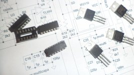
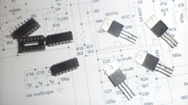
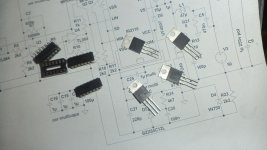
In atachment you have a PCB components, PCB artwork (redy to print), RealWorld and Schematic... Schematic of protection you have in stewin post and that schematic I use on my board...
That board is now set for full bridge for high power, You use SPK+ and SPK- to conect your speaker but you can easy change mode to stereo or paralell (two amps are on that board) than SPK+ is + for first chanel and GND is -, and SPK - is + for second chanel and GND is - . You only have to find track who is between of two resistors 10K (goes from pin 7 of TL072 to 10K who is under the board, under the chip, then goes to another 10k who goes to pin 2 ), only cut that track. Now conection for second chanel is "free" side of 10k resistor who goes on pin 2 of TL072. If you conect to input you have parallel mod if you conect to second input, you have stereo mode...
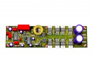
Now guide about building amp with my pcb..
-Blue tracks are gnd and I change the color that I can menage components
-All components with green pads are under the board, you put it true the holes but under und cut wires that comes out on front side but cut it all to close to front side of board.
-Jumpers are on top ofcourse, and isnt metter color (green or blue). Different color is that you can see better wher the jumepr is
I suggest you that you first soldering the jumpers, and green components than otger component, thats how you can save your nervs with my design
-All calculations for components are on right side of PCB components and Artwork, you can not mestake if you falow formulas..
-If you look closely on that board you can use TO247 transistors but you can use TO220 trasnsitors too.. For that transistors ofcourse you have to use isolators when you put them on heatsink, but VERY IMPORTANT is then you put TIP41c on heatsink you not use islotaors because case of TIP41(his colector) with heatsink is conection for GND for all components around IR2110 and TL074. If you look closely, main GND with screw nut goes to heatsink and heatsink is one BIG GND who with TIP41 provide gnd for all others components.. Its good because Heatsink on GND help to reduce parasit oscilations aronud transitors, because big case of transitors like TO247 has bigger area then TO220 and much more sensitive on parasit osilations.
-Dimension of heatsink and his ticknes you can measure when you print all on paper and use holes for srew nut to fix it on pcb..
-FB1 goes to FB1 and FB2 goes to FB2
-Conectors for led indicators, two of them (two protections) has 6 pin. This is for 3 leds. If you split that conector on 3 you will have 3 conectors with 2 pins. Every left one pin is + of LED
-Conector for second protection (Prot 2 conector) for "Active" led have to be short with conector under the reley (red one), you only falow the diagram on right side of pcb and you will figured out how to conect them (mark at the corner of conector)
-Temp Sensor is KTY81-122 and it is in TO92 case with 2 legs (without central), with wires conect them on conector on pcb and put sensor on heatsing
-Output Coil that you can use (for dimension) is T106-2, for other coils you have to use wires because its not enough space between heatsink and relays
-Leds (yelow and red) on pcb is only for power supplays when you use on example SMPS and if SMPS fail and thats led are turned off, that mean is smps fail, Rx for them is (Ucc-3V)/10mA
-Carefully calculate power disipations of resistors, you have formulas and all zeners have to be 1.3W, because now one resistor powered up two relays (currnet is double) and one resistor powered up two protestions (curent is double). All that is include in formulas for calculation but be carefull with power disipation of resistor especialy with Rrelays, Rprot (if you dont whant to calculate, the best is that both resistors be 5W)
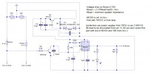
- I sugest you to build chip vu meter with AN6884 and calibrated to chow you when amp goes to true clip. On example you build amp with +-50V. Output RMS signal maximum before clip is 50V / 1.41 = 36V ~
Now, turn on your amp and play from computer 1KHz signal or any constant signal... Increase volume until you have 34VAC on your multimeter (conected on SPK+ and gnd)
When you have 34V signal, simply calibrate trim pot on your vu meter that last red led is turn on that volume of signal. Every time when you play music and some peak of signal reach that point, led will turn on and show point little before clip. Its very important because class D amps when goes to clip actually stop to oscilate and all power and curent are splitet on only two transistors and they cant hold that power without his PULSE mode...
Thats all that I remeber, if you something dont understand , just ask me