You are using an out of date browser. It may not display this or other websites correctly.
You should upgrade or use an alternative browser.
You should upgrade or use an alternative browser.
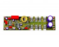
Scale able class D 1250W UCD style and Non-UCD style - PCB Ready. Tested.
- Thread starter norazmi
- Start date
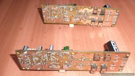
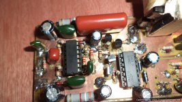
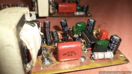
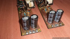
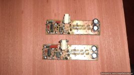
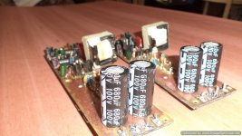
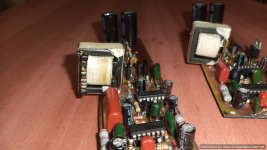
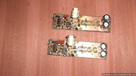
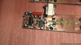
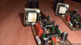
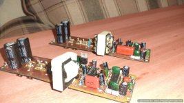
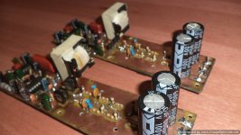
hi guys this amp non ucd is amazing and super silent , super clear and super cool i have not used a heatsink so far and my supply voltage is +/- 45vlts at 10 amps the output mosfets don't even get warm no matter how loud i try to push the amp. 
>>>>the fets i used were two pairs irf540 , two pairs irf540n and my last one was two pairs irf640n
>>>> output inductor is ee core from pc smps 18turns it got hot . i will try a bigger core ;ww:
>>>> with irf640n use 2.2nf also the output inductor warms alittle. unlike irf540 using 10nf the mosfets get cool but the output inductor gets hot
now i am going to try and use +/- 85vlts with irf 640n four pairs-)
thanks again nozrami for this wonderfull post.
Attachments
-
scalable class d single without protect schematic corrected .pdf37.8 KB · Views: 524
-
 DSC02391-Optimized.JPG155.6 KB · Views: 255
 -
 DSC02390-Optimized.JPG152.1 KB · Views: 267
 -
 DSC02397-Optimized.JPG134.2 KB · Views: 214
 -
 DSC02394-Optimized.JPG151.7 KB · Views: 178
 -
 DSC02387-Optimized.JPG150.4 KB · Views: 166
 -
 DSC02395-Optimized.JPG126.5 KB · Views: 165
 -
 DSC02392-Optimized.JPG129.6 KB · Views: 130
 -
 DSC02388-Optimized.JPG155.9 KB · Views: 137
 -
 DSC02389-Optimized.JPG166.1 KB · Views: 128
 -
 DSC02393-Optimized.JPG132.3 KB · Views: 118
 -
 DSC02399-Optimized.JPG125.1 KB · Views: 123
 -
 DSC02396-Optimized.JPG108.6 KB · Views: 130
when you refer to use full bridge it means to put two modules in paralell? Or to use a full bridge diagram ? I think the result is the same
what do you mean by parallel? No its not, it will looks like you series the amp, 2 amp each output goes to + and - to the speaker. There is no ground connect to the speaker
.Stewin, ur missing 1uf 250v caps on each rails close to mosfet into pcb, and 1uf 250v between vcc and vee. Before u go with +/- 85, try it with +/- 65 vdc, first turn on always use 10 ohm resistor 5w at each rails exclude gnd for safety reason. and watch if any component overheat. Follow the instruction component change varies with rails, look at table ucd ir2110 its the same.
paskal
New member
not in parallel, but in series. one of the modules will drive half of the load. meaning one module will see 4 ohm, another module will see another 4 ohm. they both drive the positive and negative pole out of phase from each other. each module at half the load will see you get about twice the power from each module.when you refer to use full bridge it means to put two modules in paralell? Or to use a full bridge diagram ? I think the result is the same
there's a bus pumping phenomenon that's common in all class d design. it'll be even more prominent when you try to extract high current/high power from class d and/or by running a low ohm load. suggest you read more about the bus pumping phenomenon. bridging 2 class d modules out of phase from each other reduces this phenomenon. since the non-ucd uses 4 channel opamp from the tl074 there's an option to invert one of the channel to work it out of phase. i never tested it out, but from my understanding it will work.
and also i don't think the non-ucd will work in parallel mode as there's a feedback loop at the output of the tl074/tl084 opamp to the output.
paskal
New member
did i say how AWESOME this forum is? you guys are the most awesome bunch of people that i've ever came across in *any* DIY forum.
two thumbs up for the development being done at this forum. you guys are so willing to help. never seen such willingness in an internet forum before.
two thumbs up for the development being done at this forum. you guys are so willing to help. never seen such willingness in an internet forum before.
Hi Steve can you post the PCB pdf file for the amp in post #202 ?
Thanks!
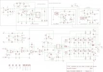
have fun. if you are going to change outputs to irf540 reduce voltage to a maxx +/-48vlts
>>and change c9 to 4.7nf up to 10nf depending on desired current you want drawn from power supply. but if you go with above 4.7nf you will need a big inductor e.g 106-2 or etd 42 because the small ee core wire heats a lot.
Attachments
-
scalable class d single without protect schematic corrected .pdf38.2 KB · Views: 432
-
scalable class d single without protect components full.pdf57 KB · Views: 389
-
 scalable class d single without protect.JPG120.5 KB · Views: 334
 -
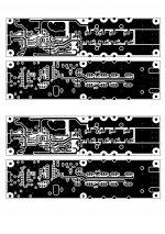 scalable class d single without protect pcb artwork.jpg256.9 KB · Views: 262
 -
scalable class d single without protect.pdf37.9 KB · Views: 363
-
scalable class d single without protect pcb artwork.pdf2.9 MB · Views: 664
-
scalable class d single without protect components clear.pdf54.8 KB · Views: 422
Last edited:
did i say how AWESOME this forum is? you guys are the most awesome bunch of people that i've ever came across in *any* DIY forum.
two thumbs up for the development being done at this forum. you guys are so willing to help. never seen such willingness in an internet forum before.
i thank GOD for lovely things such as diy forums i have learned alot and also i my self have been lucky to meet with kind spirited people
>>>> e.g luka , chas1 , andrewlebon / michelle ,opor,fibko,lorylaci,pafi,ionutzxpo,xclipse,dzony, eva,dx,n-channel, diyaudio,diysmps,htguideforums e.t.c not forgeting my favorite norazmi who led me step by step a very kind guy.
may the Almighty GOD maker of everything bless all their souls . so keep up the spirit too because by unity and putting our experiences together we come up with great amazing results e.g non ucd cold power amps and smps.
Last edited:
thanks michelle and ionutzxpoHi Steven
greetings nice to hear non ucd is performing well
warm regards
michelle
not working well only but excellent both in silence ,power and temperature of out puts . i hope ionutzxpo will try it and confirm my allegations
pls guys try this amp and bless etjale and nozrami for such a good amp
the below is my latest project to add protection and ac delay as you guys will notice the amp needs startup relay delay to avoid thump .
>>>>>>>pls guys help me out with the ac detect. how can i in co-operate the ac detect in this circuit??? and will the protect side and overcurrent temp sence work??
Attachments
Last edited:
paskal
New member
is the ac detect necessary in this circuit? the 555 reset pin is already tied to the supply rail through q2. i think that should already provide instantaneous turn off to the relay once the power is cut.pls guys help me out with the ac detect. how can i in co-operate the ac detect in this circuit??? and will the protect side and overcurrent temp sence work??
is the ac detect necessary in this circuit? the 555 reset pin is already tied to the supply rail through q2. i think that should already provide instantaneous turn off to the relay once the power is cut.
but capacitors store charge and before they discharge you may hear a sound when amp is switched off.
Hi Stewin
greetings for 5.1 volt supply caps 1mfd should be 100 volts or greater on 4 pairs how much output is expected
why .22 current sensing resistors on both sides just check ocp of TRIELL amp works good try it
warm regards
michelle
thanks andrew
Stewin, can u explane something to me!?
How can I know which value for C22 (820p original) is good? I plan to use IRFP250 for full bridge on +-50V. Which value is good for IRFB4227 on example... I use just one pair of transistors and what is the best value for that capacitor? What is swiching freq with 820p and what is on example with 4.7n?
Thanks
Stewin, there is shold be no pop since oscillation has been stop immedietly after turn off and thats what i see when i test it out, there is no pop or such.
Dzony lower the value will be increase osc freq while increase it will lower the freq osc. ie: 820pf good for 300-400 khz osc and when use 1nf then osc will be arround 200-250... with IRFB4227 is good with high freq since that fets has lower rds-on and faster. With IRFP250N u can lower is little like 1nf or else.
Dzony lower the value will be increase osc freq while increase it will lower the freq osc. ie: 820pf good for 300-400 khz osc and when use 1nf then osc will be arround 200-250... with IRFB4227 is good with high freq since that fets has lower rds-on and faster. With IRFP250N u can lower is little like 1nf or else.