Scale able class D 1250W UCD style and Non-UCD style - PCB Ready. Tested.

paskal

New member
Help!!

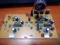
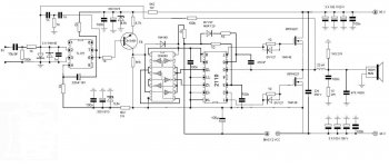
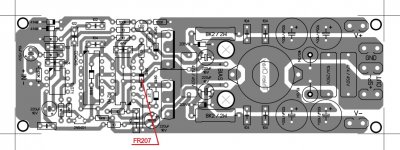
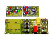
guys, i need some help over here. i tried to build the scaleable non-ucd but got into some problem. as you can see, i drew my own pcb using the schematic attached. the 12v supply follows schematic from stewin mosfet based regulator.

there's no problem with the mosfet supply and it gives around 10.6v, the board powers fine from 12v-32v and current draw is only at 0.01-0.02A across the voltage (there's no short). dc offset is at around 50mV.

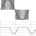
but when i feed it some music the DC offset jumps up and down to around 1.5V (no speaker connected). plugging in my test speakers all i can hear is screeching sound. when no music is playing the screeching sound is lower.

inductor is 20uH, output caps is 1uf, speaker load is nominal 6 ohm. i could plug it into a scope but i have no idea how to test this class D amp.
any advices from you guys are much appreciated.
 

Attachments

  • basic.pdf
    35.7 KB · Views: 448
  • non-ucd-2012-07-26-001.jpg
    non-ucd-2012-07-26-001.jpg
    111 KB · Views: 326

paskal

New member
i swapped the inductor to another 50uH that i have and got a silent amp without any music playing. dc offset is at 45mV. but when i start feeding it some music dc offset goes up till 15V and jumps up and down.
 

norazmi

diysmps Senior Member
paskal, 10.6v for aux supply is not enough, and what rail voltage u run with? lets say +/- 32 and R21 should be 3.3k 1w. D5 is totally wrong by using 1N4007, change it with murs @ UF @ 1N5819, it must be ultrafast diode.
 

stewin

Member
it should work perfectly do as norazmi said. but if you are usind irf540 change c3 to 4.7nf or else the 540's will be hot even at idle
 

paskal

New member
paskal, 10.6v for aux supply is not enough, and what rail voltage u run with? lets say +/- 32 and R21 should be 3.3k 1w. D5 is totally wrong by using 1N4007, change it with murs @ UF @ 1N5819, it must be ultrafast diode.
it should work perfectly do as norazmi said. but if you are usind irf540 change c3 to 4.7nf or else the 540's will be hot even at idle

thanks for the reply guys. i changed D5 to UF1007 (can't find uf4007 locally and uf1007 is comparable), r21 to 3.3k and c3 to 1.2nf (i don't have anymore 4.7nf). i still get a faint distorted sound while the music is playing and dc offset follows the musical signal. kindda like the music signal is in DC and not AC.

the inductor not doing a proper job in converting the DC pulses into AC?
 

paskal

New member
i've rechecked the schematic to pcb conversion. it's perfect without any unconnected nets. resistor values are also correct. zener diodes have been replaced with new units. inductor double checked to 20uh and 50uh values. the only thing that i could think of that might be the culprit is the output mosfet gate diodes. i'm using 1N4148. must i use 1N5817?
 

paskal

New member
try change TL074, its better if u use socket for the IC. 1N5817 is better than 1N4148.
i've populated the other channel with a new TL074, new mosfets, new mpsa92, new diodes and still got the same distortion. offset is <50mV with no input but goes up and down with music playing. the output have a distorted sound but you could make out the song that's playing.

gonna have to buy some 1n5817, a few more ir2110 to test.
 

paskal

New member
Look at pcb design again, you maybe have mestake on pcb, try to use another IR2110
Also look at capacitors, electrolicitc, when capacitor is not good same think like in your amp colud hepen...
thanks for the reply and help guys! finally traced the problem to the ir2110.
maybe it got burned during soldering. if indeed it got burned then that would be the first time i've ever burned anything during soldering. hehe.

the amp now works, tho i'm getting about 180mV of dc offset at the output.
 

Dzony_988

New member
I think 2.2k resistor who goes to gnd from tl074 (part wher is feedback) is resitor for gain. If that resitor we conect serial with capacittor 100uf (negativ pin goes to gnd and positiv to 2.2K) I think we can reduse DC offset for half...
 

apollo10

New member
Anybody has this amp simulated in Ltspice? Norazmi, if you simulated this amp, could you send me the project, please? I wanna play a little with the voltages :D
 

systemjol

New member
Hello guys.i need the help of youi make the ucd with LM311 and IR2110 described at the beginning of this article and i have a problem. the waveform before inductor signal pwm looks normal, but when I check after the inductor (the connector on the top speaker) wave appears only the lower portion, with a sinusoidal signal at the input of the amp, the positive portion of the signal just gets lost between the filter .a voltage is also regulated by TIP41C ranging between 8v and 10v maximum, had to change the zener 12v to 15v and still is but everything else seems normal 10v. mosfets I'm using are irf640, but also used other already, they do not tell me somebody.somebody because the signal is being hacked? from thanks to everyone already.
 

Attachments

  • Sem título.jpg
    Sem título.jpg
    12.8 KB · Views: 67

paskal

New member
Yes, that would be nice to post project here :)
BTW can use mur120 or egp20 instent uf4007?
in some (most of the places) i think we can interchange the fast recovery diodes. i see people using byv27, in4148, in5819,in5817, mur120, fr207 and the such in a lot of places.

Hello guys.i need the help of youi make the ucd with LM311 and IR2110 described at the beginning of this article and i have a problem. the waveform before inductor signal pwm looks normal, but when I check after the inductor (the connector on the top speaker) wave appears only the lower portion, with a sinusoidal signal at the input of the amp, the positive portion of the signal just gets lost between the filter .a voltage is also regulated by TIP41C ranging between 8v and 10v maximum, had to change the zener 12v to 15v and still is but everything else seems normal 10v. mosfets I'm using are irf640, but also used other already, they do not tell me somebody.somebody because the signal is being hacked? from thanks to everyone already.
this is what i've gathered from diyaudio on how to check the IR2110 class d operation:

If I were you, I will not connect the feedback loop before you find everything is okay, especially with a new design. I will first disconnect the MOSFET, drive an AC signal (using computer sound card playing sine wave) into the comparator. Even without a scope but a DMM, you can still check whether there is AC output from comparator, then check level shifter, then logic input to IR2110. Short Vs of IR2110 to COM. Check both low side and high side output of IR2110. If everything okay, I will then disconnect VS and COM and connect the MOSFET. Try drive the AC signal frequency as high as possible, otherwise the bootstrap power supply for the high side may not work. Measure the current drawn by the MOSFET and temperature to guess whether there is shoot through. Check MOSFET output and inductor for AC. If everything is okay, I will then close the feedback loop.
too bad i burned all of my 2110 before stumbling upon the post. now have to wait for more of them to arrive.
 

paskal

New member
anyone tried the IRS900 from diyaudio? it's even simpler than our non-ucd with a single opamp, an inverter and an ir2110. high quality pcb with overlay are attached together with the schematic.

originally posted in diyaudio class d section, designed by detex audio of thailand if i'm not mistaken.
 

Attachments

  • latest IRS-900D _ Overlay.pdf
    104.3 KB · Views: 600
  • IRS-900D _ PCB 2 thienchay.pdf
    97 KB · Views: 569
  • CHE-900D.jpg
    CHE-900D.jpg
    93.2 KB · Views: 532
  • overlay.jpg
    overlay.jpg
    166 KB · Views: 388

stewin

Member
guys protection version . but because of protection my board has become big . but i have fallen in love with this amp so i don't mind. please post opinion and feel free to make it.

i will upload the components later in the day.

have fun all GOD bless you all
 

Attachments

  • scalable non ucd class d single with protect custom sink pcb bottom.pdf
    112 KB · Views: 680
  • scalable non ucd class d single with protect custom sink.JPG
    scalable non ucd class d single with protect custom sink.JPG
    182 KB · Views: 476
  • scalable non ucd class d single with protect custom sink pcb top.pdf
    117.3 KB · Views: 608
  • scalable non ucd class d single with protect custom sink schematic.pdf
    62.2 KB · Views: 716
Top