1kW smps project (based on MicrosiM design)

MicrosiM

Administrator
Staff member
Etd

Frequency: 100kHz
Transformer: ETD34 Epcos N87 material

That looks OK.

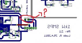
I dont know why you are using those small capacitors at +- 320VDC, center tap goes to transformer, I am not sure if they are capable of delivering the required amount of current.

You are asking for 400W, witch is very easy to get from ETD34 @ 100KHz.

Normal voltage drop for most of the SMPS units is around 10 ~ 12V per rail, that drop when loading SMPS with around 2000W, like mine

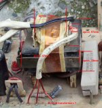
Dont know if you can make a SMPS as prototype, you can inspire from the one here to take ideas. with IR2153D, first attempt of ludo.

Wire you are using in transformer? Litz?
Turns ratio?
Winding order?

how much voltage drop you have at what load?

Hope that helps...
 

lorylaci

New member
I am using stranded-wire. I hava a lot of wire with 0,3-0,4mm diamater, I twist them together to have enough area. Primary was wound with 0,5mm^2. Secunders are wound according to what output voltage I need. Windind order is interesting, the primary and secondary is half-overlapped to get the correct leakage inductance.
I simulated the loads in Multisim, and according to that my votlage drop (no-load to half-load about 15-20%) is mostly because the leakage inductance.
Next time i will use less leakage inductance, and design a simple overcurrent protection. (a shunt and a transistor, which pulls down Ct, as voltage on shunt reaches 0,6V)
So far all my supplies worked very well, but I want to decrease the voltage drop (to less than 10%)
 

MicrosiM

Administrator
Staff member
I am using stranded-wire. I hava a lot of wire with 0,3-0,4mm diamater, I twist them together to have enough area. Primary was wound with 0,5mm^2. Secunders are wound according to what output voltage I need. Windind order is interesting, the primary and secondary is half-overlapped to get the correct leakage inductance.
I simulated the loads in Multisim, and according to that my votlage drop (no-load to half-load about 15-20%) is mostly because the leakage inductance.
Next time i will use less leakage inductance, and design a simple overcurrent protection. (a shunt and a transistor, which pulls down Ct, as voltage on shunt reaches 0,6V)
So far all my supplies worked very well, but I want to decrease the voltage drop (to less than 10%)

Wires seems good

But leakage inductance is huge, If you dont mind showing some oscilloscope waves, it will be great.

you didnt answer my question regarding those two capacitors
 

marcosaq

New member
Hi ludo3232 and MicroSim ...

Firstly I want to congratulate you on the project that you two have developed, I really liked the last layout, I start building this SMPS but you guys have tested the latter model layout?

I need this to work with SMPS with dual voltage 110/220v is this possible?

I built some SMPS here and had problems with protection against short circuits because before disarming always burned some of my output rectifiers ... this happens with this project?

Sorry I'm in Brazil and I have good English.


Thanks


Mark
 

MicrosiM

Administrator
Staff member
Hi ludo3232 and MicroSim ...

Firstly I want to congratulate you on the project that you two have developed, I really liked the last layout, I start building this SMPS but you guys have tested the latter model layout?

I need this to work with SMPS with dual voltage 110/220v is this possible?

I built some SMPS here and had problems with protection against short circuits because before disarming always burned some of my output rectifiers ... this happens with this project?

Sorry I'm in Brazil and I have good English.


Thanks


Mark

No

SMPS is protected against Short circuits. and it will not blow.

Last layout, is same as old, no one tested it. you can review it and check it your self! there is NO errors

You should do some work!! we cant do it all

Any help, we are all here!

Just Ask!
 

mrperform

New member
Today i´ve decided to make this smps for my leach superamp and i can´t understant 1 poin is the smps pcb:. where do i have to connect those 2 lines which comes from protection board?
And please tel me if there are some components that needes special material contruction like capacitors with low esr or ceramic capacitor ar other special components.
Thank you and i hope to make it without unpleasant events. ;)
 

Attachments

  • what.jpg
    what.jpg
    25 KB · Views: 494

ionutzxpo

New member
English- Hello mrperform,the 2 points are from the secondary of the curent transformer

Romanian -Salut mrperform,cele 2 puncte de conexiune sunt de la traful de curent (acolo vine conectat secundaru trafului)
 

maxente

New member
Great smps !

Hello everybody. Sorry for my english
I like this SMPS and i decided to build one
i found a transformer from an old 286 PSU
i don't know what kind of trafo is maye microsim or other user can tell me what tipe is and i found some current trafo on pcb also (i gues those are current trafo, right? )
i attached a pict whit some approximate dimensions and please tell me if those trafo's are good for this 1kw smps
Thank you very much!

on that big trafo it is write ''3750 V RMS'' and EIA 343 MEXICO
 

Attachments

  • IMG_33.jpg
    IMG_33.jpg
    232.8 KB · Views: 694
Last edited:

MicrosiM

Administrator
Staff member
Hello everybody. Sorry for my english
I like this SMPS and i decided to build one
i found a transformer from an old 286 PSU
i don't know what kind of trafo is maye microsim or other user can tell me what tipe is and i found some current trafo on pcb also (i gues those are current trafo, right? )
i attached a pict whit some approximate dimensions and please tell me if those trafo's are good for this 1kw smps
Thank you very much!

on that big trafo it is write ''3750 V RMS'' and EIA 343 MEXICO

I really dont know if that core will work, but for sure it will do something around 300W.

Again, its very difficult to know since we dont know the technical specifications of such core.

You can give it a try, LUDO will show last updated version of this SMPS in 2 weeks or so.

Thank You
 

marcosaq

New member
Hi ludo3232 and MicroSim...

Congratulations on the project, I built and am testing your project, I built the transformer primary (16x2 with 5 turns 0.4mm wire) and secondary (11x2 with 6 turns 0.4mm wire), is working ... but I realize that is not regulated output voltage drops significantly and also will deliver a horny well above the calculated and the transformer is heating up enough.

The regulation system with zener, TL431 and opto coupler is not resolved it?

The transformer is built correctly?


Thank you for your attention

Marcos
 

MicrosiM

Administrator
Staff member
Hi ludo3232 and MicroSim...

Congratulations on the project, I built and am testing your project, I built the transformer primary (16x2 with 5 turns 0.4mm wire) and secondary (11x2 with 6 turns 0.4mm wire), is working ... but I realize that is not regulated output voltage drops significantly and also will deliver a horny well above the calculated and the transformer is heating up enough.

The regulation system with zener, TL431 and opto coupler is not resolved it?

The transformer is built correctly?


Thank you for your attention

Marcos


Regulation has nothing to do with heat.

I would like to take a look at your setup first, some pictures. what core you are using?

more information's please.
 

Adonix

New member
Hi Ludo, Microsim and everyone.

I have some questions regarding this SMPS.

1. How the supply voltage is maintained at the specified value if there is no feedback/regulation? Does that mean that the SG3525 is working at a duty cycle of 50%?
2. What's the efficiency of this SMPS and it's power consumption at low load? (This is an important fact for myself)
3. If i use an ETD44 instead of ETD49, will a be able to get a power between 500-700W?

Thanks :)
 

MicrosiM

Administrator
Staff member
1. How the supply voltage is maintained at the specified value if there is no feedback/regulation? Does that mean that the SG3525 is working at a duty cycle of 50%?

Yes, 50% duty cycle.
Voltage change is done by changing transformer winding's ratio.


2. What's the efficiency of this SMPS and it's power consumption at low load? (This is an important fact for myself)

Ludo Can answer this, but I think its around 85~ 90%

3. If i use an ETD44 instead of ETD49, will a be able to get a power between 500-700W?

ETD44 will hit 800W very easy.


Hope that helps
 

luchni

New member
If you are building your first amplifier, i would suggest that you use a classic power supply, just a transformer, a rectifier bridge and filter capacitors. The price of a good classic PSU and this unit are about the same, but component availability isn't, and that's one of many problems for a DIY enthusiast. If you are new to electronics then start with simple things, as this is not a 'piece of cake' project even for an experienced builder.
Happy building and i hope your project comes to life :D
 

MicrosiM

Administrator
Staff member
If you are building your first amplifier, i would suggest that you use a classic power supply, just a transformer, a rectifier bridge and filter capacitors. The price of a good classic PSU and this unit are about the same, but component availability isn't, and that's one of many problems for a DIY enthusiast. If you are new to electronics then start with simple things, as this is not a 'piece of cake' project even for an experienced builder.
Happy building and i hope your project comes to life :D

Luchni

Have you completed your SMPS project?


Mariano,

If you have the parts, you can start making this SMPS, but this SMPS needs experience!
 

luchni

New member
Hi MicrosiM,

no i haven't, there are some things i need to get first. A new multimeter, soldering station and other crucial equipment. I was very eager to get this project going, but college and work are more important at this time, so hobbies are currently put on hold. But i'm following this forum every day, apsorbing new ideas and learning along. I'm very interested in TO-247's 600W SMPS, any news about that?
 
Top