Hyper2283
New member
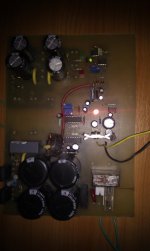
I tried to start the SMPS, I used a test transformer, without coupling 220 V~, and I put a low voltage from a transformer. The relay is coupling and the led from protection card is ON. On the scope I see no trace of switching on the transformer primary . What could it be? What are the critical steps by which to test the functionality of the source? Please help. Thanks.