1kW smps project (based on MicrosiM design)

MicrosiM

Administrator
Staff member
Microsim,
is there any rule what primary inductance should be in a halfbridge?
I think it doesn´t matter because the energy is not stored in the trafo but straight in the filter choke and caps, am I right?

Actually the leackage inductance may affect the design in one case, the RESONANT SMPS.

I never had any issues with primary inductance, during my tests.
 

kanon

Member
ok layout test is only

(1) can give me that power etd39
(2) got several of these on ebay
(3) if for a friend who repairs car amp.
(4) would indicate that wire I bought Litzy
(5) thanks.
 

Attachments

  • c1.jpg
    c1.jpg
    4.6 KB · Views: 55
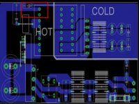
  • LAYOUT2.jpg
    LAYOUT2.jpg
    20.1 KB · Views: 290

Khron

New member
Yes, that was the part i was talking about. Now, on the layout, move the ETD to the "south" (down), and move that capacitor to the "east" (right), so there's maximum distance between the tracks connected to its legs.
 

luchni

New member
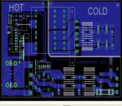
Finally i cought some time, i've been busy these days so here's the pcb with the protection circuit on it, as promised. I know it's not continous and fluent in design, sure it has flaws, but i for one am glad this is over. By the looks of it, Khron's PCB will be better than this one, as he clearly knows his business. I'll put the names and values later, just a snapshot for today.


carampman

New member
I am also interested in this as a 100 amp at 13.5 volts for servicing car amps. I used to do it for all of the local shops back in the early-mid 90s. I would like to replace my home made 120 amp 14 volt linear beast with a nice small smps. The old supply weighs about 120 pounds and takes up a lot of space. I would be interested in buying some boards when you get them done.

Thanks, Steve
 

carampman

New member
Forgot to mention: the reason is there is a sort of cult following to use the old (85-95) USA made amps right now and people are bringing them to me to repair/spec them.
 

Khron

New member
For such high currents at such low voltages, i'm quite POSITIVE you'd be MUCH better off with some method of synchronous rectification on the secondary. You can easily find low-voltage MOSFET's with single-digit mohm Rds(on) (under 1eu/pc at Digikey), rather than the ~0.75v drop over a Schottky diode.

Even so, you'd have to have parallel 60amp double-diodes (starting at over 2eu a piece at Digikey), not to mention dissipate a good few tens of watts (or maybe even over 100?). And i haven't even mentioned the copper losses in the transformer. And let's just say i wouldn't trust a pair of TO-220 devices on the switching side, for these power levels...
 

luchni

New member
here are all the pcb files, if there's some component value you can't read, find ludo's files as i don't have much time these days to correct that. pay attention to the LED's orientation (clear type ones have different pinout than the blurred ones - my experience so far)
 

Attachments

  • PCB.pdf
    44.2 KB · Views: 1,429
  • PCB color.pdf
    110.8 KB · Views: 1,417
  • PCB silkscreen.pdf
    51.5 KB · Views: 1,210
Last edited:

kanon

Member
if Esim has several demos and there is no reason to doubt but if it is diysmps arie of 70 amp mosfets to the sale which is so to provide, not whether a party water supply atx 40 Amp with any processing sinple who cares get 100Amp even etd39. we'll see not going to explode (lol do not think an isolation transformer tego ..) sldos
this for testers not for mass production..
 

luchni

New member
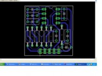
here's the updated version of the pcb with 0.8mm tracks. the rectifier model i used is the GSIB-5S package (found one convenient bridge at farnell 25A/600V)

@vikramjoshi
make whichever you like better, they are basically the same, with the exception that my version hasn't been tested, but it's still functional.
 

Attachments

  • PCB.pdf
    45.8 KB · Views: 1,267
Last edited:

kanon

Member
300w is too good to get started as the first test.

I am attaching another piece of data where you can calculate the output filter inductor over MOSFET sw.

If you like to open a new (post) for the PFC to build a 1kw.

More than one insurance can help us do it .. :eek::eek::eek:
 

Attachments

  • MC33260.pdf
    84.3 KB · Views: 752

ludo3232

Member
Hi all!

i have made new revision of PCB for fixing problem of long tracks to mos and others..

It's based on same schematic of later version

I have decided to share with you the new pcb.

if anyone make copy of this pcb, keep for you, thanks.

certain values are no good readable, i fix it later and post updated files

Warning, PCB are no tested yet!!
 

Attachments

  • smps v3.11 PCB.pdf
    42.4 KB · Views: 1,801
  • smps v3.11 Top.pdf
    68 KB · Views: 1,665
  • smps v3.11 parts.pdf
    26.8 KB · Views: 1,465

luchni

New member
Excellent job Ludo, it looks pretty good. I guess that the protection card uses the same layout? Could you make the pads on the small resistors capacitors and diodes bigger (like 2.1844) in the updated version, that would be great.
Keep up the good work :)
 
Top