1kW smps project (based on MicrosiM design)

Khron

New member
Khron, you probably have some error in there, the way you have it now the mosfets short the bulk caps.

*Uber-facepalm* Ach, thanks for spotting that >_< It's been a rough week last week, i guess i was far from my best when copying the schematic...

:w)
 

luchni

New member
As i was making a list of components and checking them at my local 'electronics stuff' shop i got very disapointed with their offer. Specifically the big caps, since the highest value is 470uF/385V (30mm diameter) and it's the only one with that voltage rating and a price of 15 euro (!!!!), the IR2110 chip is around 6.5 euro (!!), they don't have IRFP460, or any of the MUR diodes nor any replacement. They have everything else (thank God).


Edit:
Just had an idea: what about those caps from ATX supply's? 330uF 400VDC? I have a friend with a lot of working and broken ATX supply's, he just strips the board for components. I know they are (probably) old, but would they suffice? Don't have an ESR meter though... :confused::confused:
 
Last edited:

IGBT

Switching Fanatic!
As i was making a list of components and checking them at my local 'electronics stuff' shop i got very disapointed with their offer. Specifically the big caps, since the highest value is 470uF/385V (30mm diameter) and it's the only one with that voltage rating and a price of 15 euro (!!!!), the IR2110 chip is around 6.5 euro (!!), they don't have IRFP460, or any of the MUR diodes nor any replacement. They have everything else (thank God).


Edit:
Just had an idea: what about those caps from ATX supply's? 330uF 400VDC? I have a friend with a lot of working and broken ATX supply's, he just strips the board for components. I know they are (probably) old, but would they suffice? Don't have an ESR meter though... :confused::confused:

hmm

Those 330uf Capacitors will not be OK for 1200W Power ratings, thats bad. You can use them I think with low power around 300W

you can get any fast diodes close to MUR, But I think PC SMPS has many fast diodes, open one and check it

ESR not that critical here
 

luchni

New member
Sorry, my mistake, i meant parallel connection, but now i see that 6 caps per rail is too large for the pcb... this is going to be a big problem, distrelec doesn't have any apropriate ones, and ebay doesn't promise much either (found nippon 1800uF 400VDC, but that's it). I found some BYV42-200 double diodes i had. But no worries for now, as i have to study hard for the next two months, exams and what not (thus the delay with the pcb).
But i'm in no hurry, maybe some new ideas will come up for this project that i'll be able to implement. A good preparation is best for success. :D
 

luchni

New member
After the disapointment earlier today, i found out that Farnell has a representative in Croatia, they have everything i need, but that comes at a higher cost. I guess i'll have to get a piggy bank as soon as possible :D:D:D


Edit:
Updates on the PCB - rotated the oscillator and FET driver layout 90' clockwise, gained much space on the board, the protection circuit fits nicely now, less jumpers less, shorter tracks to G of the FET's, minor adjustments. I feel like this is finally coming to an end. Thought about adding Elektor's soft-start circuit on the board, that would be a nice add-on (or am i getting ahead of myself :))
 
Last edited:

luchni

New member
Thought about adding Elektor's soft-start circuit on the board, that would be a nice add-on (or am i getting ahead of myself :))


Sorry for multiple posts and self quotations (moderator, please moderate), found out it can be done with SG3525, no need for external circuits...
 

kubeek

New member
luchni, look at my schematic here to see how to control the softstart by ovecrurrent protection, it basically discharges the softsart cap and holds the shutdown pin high.
 

Hyper2283

New member
Can anyone tell me what is the value of the resistance R1 from card? also adjustable potentiometer????sorry for many questions.
 

MicrosiM

Administrator
Staff member
Can anyone tell me what is the value of the resistance R1 from card? also adjustable potentiometer????sorry for many questions.


R1 across the diodes is not that necessary, its used to adjust the current limit, use 330 OHM as start, and adjust later.

POTMETER use 10K
 

Khron

New member
Just a quick update: i think i'm pretty much done with the PWM + OCP board. On my "main board" this will "plug in" right near the FET's. You'll see what i mean when i'm done with the main board as well :)
 

Attachments

  • Untitled.gif
    Untitled.gif
    78.2 KB · Views: 873

Khron

New member
Ah, what the hell, i'm in a "generous" mood :D 
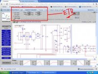
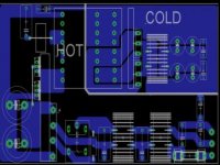
Here's how far i got with the main board, as well.

You might spot a few differences:
1) As i've mentioned before, i found a 2x9Vac transformer in my closet that's a different size to the EI38 on ludo's board
2) I've also got some vertical (F456) fuse holders; quite handy for saving some board space
3) i'm switching the relay through an npn transistor, since i only have a few 24v relays in my "stock", so... Why not put them to use? :)
4) i'll need this to be a single-supply (not symmetrical), so just one output (but with two connectors each)
5) You'll also spot some input filtering. In addition to that, i'm planning to use some "scavenged" IEC sockets from computer smps's, with attached X/Y caps

I haven't yet decided if i'll try to source a 7815, or i'll stick in a LM317 regulator in there...

So far, the big board's around 15x15cm
 

Attachments

  • Untitled2.gif
    Untitled2.gif
    52.9 KB · Views: 423

kanon

Member
try to make this calculation and gave me the following with a etd39 get that power amps.
with poweresim ...
I am fan but I have some knowledge of electronics ..
then a 100Amp etd44 if I can get to 13.5V
thanks for reading my question .. greetings
I'm trying to 1r2153d or I have another option with TL494
half-bridge. few (cm2) etd44 that part confuses me
sorry for ingles google translater..!

ac input vinmax 160 vrms
vinmin 60 vrms
v01 13.5v
l01 100a
95khz
 

Attachments

  • et39.jpg
    et39.jpg
    20 KB · Views: 494
  • LAYOUT1.jpg
    LAYOUT1.jpg
    19.6 KB · Views: 484
Last edited:

Khron

New member
1) Why do you need 13.5v / 100A ? For some car amplifiers or something?

2) In the layout, i see a Y-capacitor between the primary and secondary, with almost NO isolation :eek: Move the transformer down, and move that capacitor to the right!
 

kubeek

New member
Microsim,
is there any rule what primary inductance should be in a halfbridge?
I think it doesn´t matter because the energy is not stored in the trafo but straight in the filter choke and caps, am I right?
 
Top