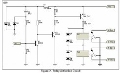
Ok so now I have the totem pole stage working properly!! ") Check out the photos below! All those resistors you see on the breadboard are actually four 27 ohm resistors in parallel to get me 6.9 ohms. Just like the R7 and R8 in Fig 1. The only problem is that when driving my mosfets, they still have the same stupid waveforms on them as before!! x-( This is extremely annoying and I would welcome any ideas as to why I am not able to switch these mosfets very well!
Check out the photos below! All those resistors you see on the breadboard are actually four 27 ohm resistors in parallel to get me 6.9 ohms. Just like the R7 and R8 in Fig 1. The only problem is that when driving my mosfets, they still have the same stupid waveforms on them as before!! x-( This is extremely annoying and I would welcome any ideas as to why I am not able to switch these mosfets very well!
Check out the photos below! All those resistors you see on the breadboard are actually four 27 ohm resistors in parallel to get me 6.9 ohms. Just like the R7 and R8 in Fig 1. The only problem is that when driving my mosfets, they still have the same stupid waveforms on them as before!! x-( This is extremely annoying and I would welcome any ideas as to why I am not able to switch these mosfets very well!Attachments
-
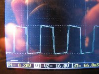 Totem Pole Waveform.jpg357.6 KB · Views: 67
 -
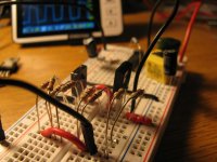 Breadboard With Totem Pole State.jpg216.6 KB · Views: 91