Some tips
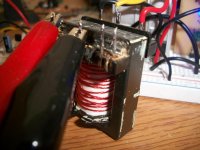
Doing some numers you have: 5 primary turns & 13 secondary turns -> Turn ratio is: 13/5 = 2.6
if you apply 12V you must have 12 * 2.6 = 31.2V at secondary minus secondary diode losses. That is correct.
Now, the fact is that if you loose only 2V for example between your power supply output terminal and the mosfets (that would be the whole primary circuit) the secondary output would be: 10 * 2.6 = 26V and since the power supply doesnt realize whats happening your secondary output will fall so you must avoid primary losses at all cost. See the protoboard as "resistive contacts" because when you place a component its contacts are not good.
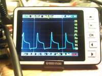
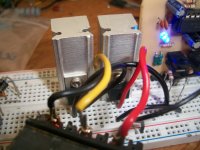
Ok, now its time to post measurings to analyse the problem. First, place and keep placed a [1K to 10K] resistor on secondary and measure output and primary input voltage where SG3525 is. You must allways have a dummy load connected, not really necessary but it keeps secondary voltages in order. Voltages with no load above 10V can be expected. This is SMPS with "no load".
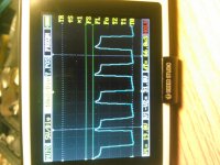
Then add the 120 Ohms resistor and measure secondary output, primary input voltage where SG3525 is. This is SMPS with load.
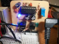
I choosed SG3525 Vcc arbitrary, you could use the pin itself of power mosfet (maybe better).
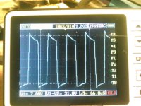
At this point you know the losses at primary, if you see you lost few volts you can expect normally ~24V due to unregulation.
If you want to test your primary circuit, a good idea is to use 2 light bulbs used in front lights of a car and connected to use both filaments, those bulbs are 55W rated and you need two because the push-pull configuration. Then you can go adding 2 more to see how they go warming and measure your power supply searching for resistances. Of course you have to disconnect the transformer to do this.
At this point you can be sure if your primary circuit is able to deliver those "X" watts you want.
I usually test things like UPSs using filament bulbs (because you can still find them here and they are very cheap).
Now looking at transformer, to answer your question, it is not saturating. Reason: If core enters saturation, primary inductance dissapears and the result is an effective shortcircuit at primary with mosfets blowing for sure!
If core is not delivering power it should be due to bad flux selection. You choosed 5 turns for primary... why? Because you started like me, trial and error. Five turns determine certain working point in the core. The idea is to determine the necessary amount of flux to deliver the power, you have to deal with some ecuations and transformer datasheet for that and i cant help you with that now...
Transformer is the heart of the power supply, it must be choosed by making a lot of compromises: Flux, area, frecuency, room for windings, isolation, etc... The goal is to get 50% of it looses in it and the other 50% in windings. That would be a perfect selection.
In real life, according to my experience, people who install real car audio power stages at home without the necesary knowledge place them at the trunk with small wire gauge usually 4mm, the same they use at homes. And when they raise volume they experience different problems because of that... then you measure wire losses between batery and power stage and you find that the power stage is trying to work with 8V or less... teaching: Wire gauges are important and they should allways be kept in mind.
Take care and have a good weekend!
 Anyways, it's unfortunately gonna be a while before I can get on with this project and do some more testing and start some actual building.