12v 250w Car SMPS based off SG3525

norazmi

diysmps Senior Member
IRF540N will work no problem, but it has rds-on about 0.44 and supply current only 33A. Irfz44N is more good and even irf3205. But let it run with irf540N n let see the power it can provide. I think u need to re-adjust gate resistor about 22 - 27 ohm for the irf540N.

Codex next time cant u find any broken computer psu? We can recycle main trafo and re-use it. :D
 

codex653

New member
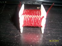
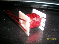
Well I had a bunch of cores from several ATX supplies but my sister's basketball had an unfortunate run-in with my workbench and destroyed all my cores when they were knocked onto the concrete floor. I wasn't too happy about that haha ((@

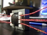
I'm not too worried about the 33A current limit...this smps is gonna be used in my car to power a 250 watt subwoofer system. Since it's audio, it won't draw a continuous 250 watts anyways and even if it did that only comes out to be roughly 21A, so im feeling pretty confident in the ability of the IRF540's to handle it.

Now why would I need to re-adjust the gate resistor?? I know it will improve the switching of the mosfet and such, I've done several experiments at home to see the effect of various gate resistors on switching waveforms, but I don't know WHY it does this...in order to turn the mosfet on, the gate capacitance needs to be charged and for a faster turn on, more current is needed. It would make sense to have a lower resistor value so that more current can pass and therefore theoretically turn it on faster...which is good. So why does increasing the value of the gate resistor slightly cause an improvement in switching?? It's one thing thats puzzled me a little bit -)
 

codex653

New member
Okkkk, I've wound the transformer tonight and here are the specs.

Primary is 5+5 turns; 8 strands of 24 gauge...Secondary is 15.5+15.5 turns; 3 strands 24 gauge. The primary and secondary are wound in opposite directions to each other so as to help increase the coupling (read that somewhere).

Assuming 13v nominal charging input voltage (alternator from the car) and 5+5 turns on the primary, that comes out to be 2.6 turns per volt. I wanted around 40 volts on the secondary so that after the rectifier diode losses, i'll still have a little bit of room to play with the voltage regulation. The goal in the end is to have a regulated +/- 35v.

The primary wire is freaking massive in my opinion and would appear to easily take the current, however only time will tell. It should only have to take at most 21A for a brief moment and about 12A-15A continuous.

The pcb still isn't made yet for this so I won't be able to test things...that's what I'm going to be working on next. I do however need to first resize the pcb so that it will fit all my components. I found after doing a quick print of the board that components were spaced way too close together. ::SD ha


Anyways, here are some pics of the transformer winding.
 

Attachments

  • 100_5087.jpg
    100_5087.jpg
    242.7 KB · Views: 140
  • 100_5089.jpg
    100_5089.jpg
    234.4 KB · Views: 119
  • 100_5094.jpg
    100_5094.jpg
    235.4 KB · Views: 138

norazmi

diysmps Senior Member
lower gate resistor will demand more faster turn on and off, look at datasheet irf540 have high rds-on than irfz44n, and lower the gate will make irf540 heat fast ( more current demand ) at high load, normal load maybe no problem but think when u reach the peak :D .

well my car alternator provide 14.5 v btw ur trafo looks great and good winding section.

regards.
 

RocketFuel

New member
Hello again. 14V for my alternator. Your transformer looks nice, nevermind about pins they are useless and it wont move with heavy gauge wire.
 

codex653

New member
I've resized the pcb so now all the components fit like they should! I should be able to make this thing on monday or tuesday this week...dunno yet. Can't wait to start testing! :)

I would upload the image of the pcb, but the attachment manager is not working properly right now....
 

codex653

New member
lower gate resistor will demand more faster turn on and off, look at datasheet irf540 have high rds-on than irfz44n, and lower the gate will make irf540 heat fast ( more current demand ) at high load, normal load maybe no problem but think when u reach the peak :D .

well my car alternator provide 14.5 v btw ur trafo looks great and good winding section.

regards.

oh ok makes sense! weird...my car's alternator must just be an oddball haha
 

codex653

New member
I decided to wind a second transformer because I had an extra core that I ordered and wanted to compare winding techniques! On the first transformer, I had wound the wire twisted together to make one giant single wire. On the second, I decided to try laying the individual wires side by side like I have seen done in commercial switching supplies. I posted some pics below of the windings. The second transformer ended up being much neater and far less "bumpy" than the first. It will be interesting to compare the performances of the two! :D

Edit: gosh dangit!! the stinking file manager won't upload my files!! When I click upload, the little bar just slides off to the right and nothing happens! This is so frustrating....
 

norazmi

diysmps Senior Member
hmm, why not test with 1st trafo that u made, try to run it and test it first before u decide to make second one, maybe there is need some adjustment or any...

regards.
 

codex653

New member
hmm, why not test with 1st trafo that u made, try to run it and test it first before u decide to make second one, maybe there is need some adjustment or any...

regards.

oh I wasn't building a second one because I thought the first wouldn't work. Nah, I was just curious on the various performance of the two different styles of windings. This was something I was going to do anyways cause I was wanting to learn for future reference which way is better/easier/more efficient, etc. :)
 

codex653

New member
drat....I went to go etch the circuit board for the smps and it turned crap :(...gonna have to try again tomorrow!
 

codex653

New member
ha no i didn't even get that far :p I was talking about the manufacture of the pcb! The acid solution for some reason did not work very well at all and the pcb ended up having to sit over night after I took it out of the solution...it seemed to eat through the toner so I have to start again today.
 

Redwire

New member
You have to heat etchant (ammonium persulphate, blue stuff) to 40-60C or it does pretty much nothing; ferric chloride (brown stuff) works OK at room temp. But you also have to rock the etchant (stir) constantly and it should take 7 minutes.
 

codex653

New member
Those comments would be useful, however I'm not using either of those etchants. Thank you anyways though! :) I'm using what's called cupric chloride and it's made by combining two parts hydrogen peroxide to 1 part muriatic/hydrochloric acid and then etching. The etching produces the cupric chloride which in turn further etches the board. It works very well and is rechargeable, unlike many other etchants! I found out however that if you use 3 or even 4 parts peroxide to 1 part acid it makes the solution EXTREMELY strong and it etched a 6x6 inch 2oz single sided board in about 2 min!! :eek:

I got the toner to stick much better this time and the board turned out extremely well. I've already populated and tested the input caps, filter, and driver board. Next I need to move on to testing the mosfets and make sure I got a clean signal on the gate. Pics will come later if this website will let me upload them!!x-(
 

codex653

New member
yup norazmi you were right about the gate resistors! :) they certainly DO need to be higher! I thought I would try the original just thinking "ehh what the heck i'm curious" and the waveform on the Drain does NOT look right! :D ha but i've seen it before and if i can find it, i'm gonna raise the gate resistor to 33 ohms and see how that works. Not sure if i'm going to get to it today however.
 

codex653

New member
well it turns out I was able to get to it and changed out the resistors. Couldn't find 33 ohm and had to settle for 27 ohms. Believe it or not, it actually got worse than with the 4.7 ohm gate resistors. The gate drive frequency went down from 50Khz to 11Khz, the mosfet's heatsink significantly heated up, and the Drain waveform was terrible! I'm dreading that something is wrong in the transformer as I've had absolutely no experience winding smps trannys before... :(

found out if i stick a purely resistive load where the transformer is supposed to be, the mosfets suddenly become quite happy and will have a very nice and clean waveform...what the heck do I do here? This would be a great situation for me to already be an engineer! ha :D
 
Last edited:
Top