You are using an out of date browser. It may not display this or other websites correctly.
You should upgrade or use an alternative browser.
You should upgrade or use an alternative browser.
12v 250w Car SMPS based off SG3525
- Thread starter codex653
- Start date
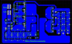
New and Improved PCB!
K so I redid a lot of things on the old pcb. First off, I hated that I was going to be building a double sided pcb with through hole components. Thats just too messy for me and I don't think it looks as nice, so I rewired everything to make it be a single sided board.
-Bigger and shorter power traces
-More input caps
-Full Wave Rectifier output now
-Put in the chiseled corners (thanks rocketfuel!)
I think this is a big improvement over the last pcb
Attachments
-
 250W SMPS Board Rev 2.JPG149.3 KB · Views: 164
RocketFuel
New member
Thats better now. Another tip: Use TO-220 Rectifiers (the ones with two diodes) ... they are not cheap, but they are small, support big currents and you can easily place them in every pcb.
Getting prototype pcb's made
I've found BatchPCB is cheap, compared to other PCB houses.
$10 setup fee, 2 layer - $2.50/sq. inch, 4 layer - $8.00/sq. inch.
Cons: they take weeks for them to arrive, fixed at 1oz copper and 0.062" FR-4. Sometimes I would like thicker for SMPS.
If you know of any other low-cost PCB houses, let us know.
Some ideas on your pcb layout...
You will need heatsinks for the mosfets and rectifiers. Like ones from a junked ATX PSU? Bare TO-220 can dissipate about 1W for 88°C.
Then think about how you will get a screwdriver in there - the rectifiers are blocked by the filter caps. etc.
I would add a fuse holder (clips), and 4x pcb mounting screw holes.
Not sure how you turn this off/on, but it's cheaper to cut power to the 3525.
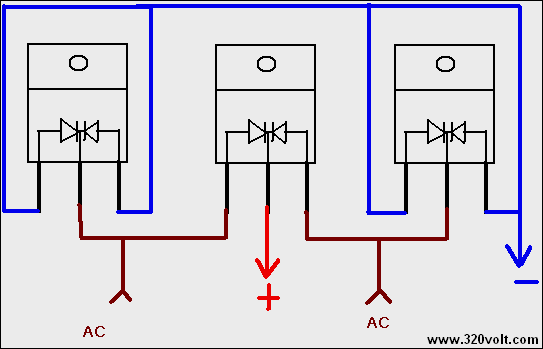
Here is pic of a bridge rectifier using dual diodes:
You will need heatsinks for the mosfets and rectifiers. Like ones from a junked ATX PSU? Bare TO-220 can dissipate about 1W for 88°C.
Then think about how you will get a screwdriver in there - the rectifiers are blocked by the filter caps. etc.
I would add a fuse holder (clips), and 4x pcb mounting screw holes.
Not sure how you turn this off/on, but it's cheaper to cut power to the 3525.
Here is pic of a bridge rectifier using dual diodes:
RocketFuel
New member
Here I post usefull data from my SMPS book about secondary and rectifiers:
"Having determined the number of turns of each output needed to produce the desired output voltages, the designer must now consider the physical arrangement of the secondaries that would meet the specified needs. Three general arrangements can be considered, as shown in Figure 6.6. Each of these arrangements affects in a small way the efficiency of the supply and the volume of wire that will be used within the transformer and the transformer cost. Figure 6.6(A) is the most common form of secondary arrangement. It has the advantage of having only one diode loss during each power conduction period. The windings themselves are operated in a half-wave fashion and hence have to carry only half the average output load current, so the wire gauge can be smaller. But each half-wave section of the winding has the full number of turns to develop the output voltage. The non-center-tapped secondary arrangement shown in Figure 6.6(B) has half the turns on the core when compared to the center-tapped arrangement, but it now has two diode drops during the power conduction cycle and the wire gauge is larger. So from an efficiency standpoint it exhibits slightly more diode conduction and switching losses than the center-tapped secondary and is higher in component cost but less expensive in labor costs during the manufacturing of the transformer."
http://s8.postimage.org/rx74lq5tx/Dibujo.png
In my experience, I preffer 6.6(A).
Take care!
Redwire: Yup definitely plan on including heatsinks! wouldn't dare run it without them! ") hmmm maybe i'll space the caps and diodes slightly so that i can fit a screwdriver in between there. Yah I still need to add all the fusing and mounting holes. I was more focused at the time with the actual circuit layout and was going to add that stuff later. I don't know of any other pcb manufacturers mainly cause i've never used one before. I make my own boards and they turn out pretty well i think, though obviously not as good as a professionally made one.
hmmm maybe i'll space the caps and diodes slightly so that i can fit a screwdriver in between there. Yah I still need to add all the fusing and mounting holes. I was more focused at the time with the actual circuit layout and was going to add that stuff later. I don't know of any other pcb manufacturers mainly cause i've never used one before. I make my own boards and they turn out pretty well i think, though obviously not as good as a professionally made one.
Rocketfuel: Hmm yes 6.6A sounds like a good arrangement! For the dual polarity version, it would be two of 6.6A with the center taps connected together correct?
Idk, I may or may not use the dual diodes...on previous board i had dual diodes and there was a really weird wiring configuration on the pcb. But I'll try again and see what I get.
hmmm maybe i'll space the caps and diodes slightly so that i can fit a screwdriver in between there. Yah I still need to add all the fusing and mounting holes. I was more focused at the time with the actual circuit layout and was going to add that stuff later. I don't know of any other pcb manufacturers mainly cause i've never used one before. I make my own boards and they turn out pretty well i think, though obviously not as good as a professionally made one.Rocketfuel: Hmm yes 6.6A sounds like a good arrangement! For the dual polarity version, it would be two of 6.6A with the center taps connected together correct?
Idk, I may or may not use the dual diodes...on previous board i had dual diodes and there was a really weird wiring configuration on the pcb. But I'll try again and see what I get.
RocketFuel
New member
My mistake... I did a quick replay and didnt read what Redwire posted before... there you have how to do it using 3 TO220 dual diodes... At least keep in mind what i posted about secondary windings and rectifiers!
Yeah I'm definitely going to be using the winding stuff you showed me. I'm gonna have to get new ferrite and bobbins now cause my little sister was kind enough to accidentally drop my transformer on the concrete. Oh well, time to upgrade -)
I believe I'm going to end up using the single diode TO-220 package for this first prototype for two reasons.
1. Cost...the single diodes are much cheaper than the bigger dual diodes
2. PCB layout...with the dual diode package, the layout for the rectifier lines was awkward and just didn't look right. The singe diode package takes up the same amount of space as 3 of the larger, dual diode packages, yet retains a greater simplicity with the pcb layout.
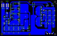
Also I posted a picture of Rev3 of the board. I added the fuses and all the mounting holes. The only thing I have left to do is get all the parts together and do a dry test of all the mounting and spacing of the components.
So far, I'm liking how this is turning out! It's been a long process but hopefully the time spent on it will reflect in the results!
I believe I'm going to end up using the single diode TO-220 package for this first prototype for two reasons.
1. Cost...the single diodes are much cheaper than the bigger dual diodes
2. PCB layout...with the dual diode package, the layout for the rectifier lines was awkward and just didn't look right. The singe diode package takes up the same amount of space as 3 of the larger, dual diode packages, yet retains a greater simplicity with the pcb layout.
Also I posted a picture of Rev3 of the board. I added the fuses and all the mounting holes. The only thing I have left to do is get all the parts together and do a dry test of all the mounting and spacing of the components.
So far, I'm liking how this is turning out! It's been a long process but hopefully the time spent on it will reflect in the results!
Attachments
-
 Main Board Rev 3.JPG163.6 KB · Views: 89
Okkk! finally have purchased all the parts for the switching supply except for the one crucial piece: the transformer! Now I've been looking around ALOT lately and have found it to be extremely difficult to find any decent place that does not require you to buy ferrites in the order of thousands at a time. However I stumbled across one website today for a company that manufactures ferrite cores in the U.S.A (go America!!). There will be link at the bottom here. Have any of you heard of these guys before? Are they reputable? Good quality products? I may just have to order to find out, but if they end up being legit, DIYers might have found a gold mine!
I linked to some of the ETD39 cores they have...pretty well priced! however shipping for an order under a hundred dollars is a flat rate $20 :/
http://tscinternational.net/390000.html
I linked to some of the ETD39 cores they have...pretty well priced! however shipping for an order under a hundred dollars is a flat rate $20 :/
http://tscinternational.net/390000.html
Well, Amidon seemed to be the best option that I could find on the internet. Went ahead and ordered two of the 200w cores and two different types of toroids. Can't wait till they come in!!
Edit: I FINALLY found a spreadsheet that listed power vs frequency for the "200w" cores. Turns out the 200w is at 20Khz, 350w at 50Khz, and 1000w at 250Khz. I'm going to be running my supply somewhere around 80Khz, so I'm in good shape! thanks norazmi!
Edit: I FINALLY found a spreadsheet that listed power vs frequency for the "200w" cores. Turns out the 200w is at 20Khz, 350w at 50Khz, and 1000w at 250Khz. I'm going to be running my supply somewhere around 80Khz, so I'm in good shape! thanks norazmi!
Last edited:
yep u got it . i`ve been ordered core from amidoncorp long time. They provide good price and shipping not too long. Last time i`ve ordered T106-2 iron powder about 50 pcs. They all in good condition. Running core about 80Khz is good at least, or stacked core for more power .
. i`ve been ordered core from amidoncorp long time. They provide good price and shipping not too long. Last time i`ve ordered T106-2 iron powder about 50 pcs. They all in good condition. Running core about 80Khz is good at least, or stacked core for more power .yep u got it
Yup! can't wait!
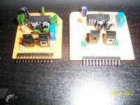
Here's a pic of the new and improved driver board compared to the older prototype version! So far from all the initial testing it seems to work like a charm!
Attachments
-
 New and Old Driver Board.jpg345.6 KB · Views: 130
nice, more compact, i`ll follow your progress. How many power mosfet u will use with this smps? (ie:IRFZ44N)
gonna end up using 2 pairs of IRF540N's initially. It should work, but if in the unlikely case I need more mosfets, I'll just upgrade. The transformer cores came in today and look fantastic! The bobbins were a bit of a let down however. I was expecting something with pins that I could solder into a board and not a 60Hz E-I lamination transformer bobbin.
It turns out I'm gonna have to resize my board to fit the transformer...its larger than expected. Once my wire and rectifier diodes coming in I'll really start being able to get this thing going.