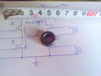
Here are the the toroids that are to be tested as soon as I obtain driver transistors for it..
at the left is the toroid which you mentioned so big, at the right is a toroid from chinese cfl so small..
View attachment 5074
Yours are exactly fit as GDT in terms of size..It looks its size is at the middle of mine
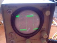
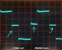
And regarding the waves you showed, I think it is perfectly good in shape..
Hoping that I can have my complete components and time to start testing those toroids of mine..
Thanks MicrosiM for your support..
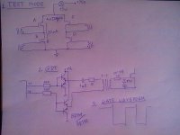
I am not using any drive circuit into my test. I used a capacitor in series with GDT primary.
But the final design should include a driver circuit.
")