You are using an out of date browser. It may not display this or other websites correctly.
You should upgrade or use an alternative browser.
You should upgrade or use an alternative browser.
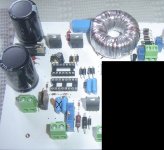
"TO-247" First Project - 600W SMPS"
- Thread starter TO-247
- Start date
Oh , My godsorry for your scope.
very very thanks for sharing somethings like this issues.
so , it's very important to use isolation transformer for powering the scope , but the smps connect directly to the main AC lines , it's right ?
No worries, I fixed the power supply of my oscilloscope.
Yes
SMPS connects to mains directly, and oscilloscope via Isolation transformer.
Dont forget serial Bulb, at first tests!
TO-247
New member
the older versions of schematics had a lot of problems and maybe not work ! the last version is here : ( 16V SMPS and SMD Parts included ) , but i'm not test it yet , i'm not guarantee the operation of circuit.
now i'm working on pcb , it's difficult.
some people working hard on projects and another people just DOWNLOAD and enjoy !
now i'm working on pcb , it's difficult.
some people working hard on projects and another people just DOWNLOAD and enjoy !
Attachments
Smps
I don't know what problems you may face in old design?
Using SMPS as AUX supply is really nice thing. I tried to make same idea before + building costume transformer, I found it useless from cost side, 3VA transformer is much cheaper!
This design is tested by ludo before and its fully working.
I guarantee that you will make a better SMPS, its clear to me that you are capable! And I am happy for you!
People like you are rare, people who work, and making research, improving things. but finally you will get the experience and results!
Thanks for the hard work you are doing, really :UP:
the older versions of schematics had a lot of problems and maybe not work ! the last version is here : ( 16V SMPS and SMD Parts included ) , but i'm not test it yet , i'm not guarantee the operation of circuit.
now i'm working on pcb , it's difficult.
some people working hard on projects and another people just DOWNLOAD and enjoy !
I don't know what problems you may face in old design?
Using SMPS as AUX supply is really nice thing. I tried to make same idea before + building costume transformer, I found it useless from cost side, 3VA transformer is much cheaper!
This design is tested by ludo before and its fully working.
I guarantee that you will make a better SMPS, its clear to me that you are capable! And I am happy for you!
People like you are rare, people who work, and making research, improving things. but finally you will get the experience and results!
Thanks for the hard work you are doing, really :UP:
TO-247
New member
I don't know what problems you may face in old design?
the pin 2(IN+) on sg3525.the 10K resistor in wrong place.
Using SMPS as AUX supply is really nice thing
yes it is , but i hope it's work good !
People like you are rare, people who work, and making research, improving things. but finally you will get the experience and results!
Thanks , it's because i'm a member of DIYSMPS and i learning useful things on this forum , also going to share useful thing to others.
TO-247
New member
no , ludo schematic is correct , please refer to this post :
http://www.diysmps.com/forums/showthread.php?182-quot-TO-247-quot-First-Project-600W-SMPS-Based-On-Ludo-s-Design&p=2353&viewfull=1#post2353
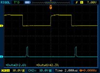
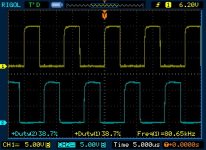
600W SMPS V.0.2 , the pin 2 of sg3525 not connected to the ground with 10K Resistor. and when i measured the voltage on the circuit , it was around 5v , but after correcting the 10K resistor , it was around 2.5V
the version 0.8 is OK.
http://www.diysmps.com/forums/showthread.php?182-quot-TO-247-quot-First-Project-600W-SMPS-Based-On-Ludo-s-Design&p=2353&viewfull=1#post2353
600W SMPS V.0.2 , the pin 2 of sg3525 not connected to the ground with 10K Resistor. and when i measured the voltage on the circuit , it was around 5v , but after correcting the 10K resistor , it was around 2.5V
the version 0.8 is OK.
Just a question, isn´t it better to power the smps through isolation transformer and leave the scope the way it is? I think that when you lift the scope´s ground and measure on mains, you are likely to have 320VDC on the scope´s chassis. Not a good thing.
Offcourse the isolation transformer would need to handle the power of the smps, but for initial troubleshooting you could do with a 100W isolation transformer just to make measurments safer.
Offcourse the isolation transformer would need to handle the power of the smps, but for initial troubleshooting you could do with a 100W isolation transformer just to make measurments safer.
TO-247
New member
Just a question, isn´t it better to power the smps through isolation transformer and leave the scope the way it is? I think that when you lift the scope´s ground and measure on mains, you are likely to have 320VDC on the scope´s chassis. Not a good thing.
Offcourse the isolation transformer would need to handle the power of the smps, but for initial troubleshooting you could do with a 100W isolation transformer just to make measurments safer.
Hi
I think some times , you need to measures a lot of parameters from your smps that loaded at maximum , then you need isolation transformer above 500W ! so the best way is use isolation transformer for powering the scope , but be careful when you working with the scope.
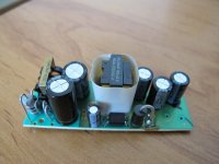
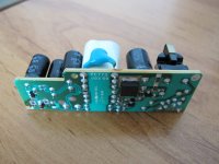
SMPS design update !
i want to use commercial 15V 1A SMPS for aux supply , it's have more reliability and quality with less space and cost. what you think MicrosiM ? it's good idea ?
Attachments
-
 15V 1A1.jpg70.2 KB · Views: 311
 -
 15V 1A2.jpg78.6 KB · Views: 227
TO-247
New member
Thanks
yes , but 10% of pcb may be complete -) it's because i'm so busy this days.
Have you started PCB design?
yes , but 10% of pcb may be complete -) it's because i'm so busy this days.
zeus_threat
Member
Just a quick question here regarding mesurements scope manufacturers recommend making differential measurements using the tip of both probes and the math function of the scope. Scope remains grounded and smps as well. I didn't see anyone mention this is there any reason?
Just a quick question here regarding mesurements scope manufacturers recommend making differential measurements using the tip of both probes and the math function of the scope. Scope remains grounded and smps as well. I didn't see anyone mention this is there any reason?
I never heard of this before, any application notes?
This looks interesting..
Microsim, you nevere used a scope in differential mode? Just set both channels to the same v/div in add mode, set one channel on invert, and go measuring
Yep, I never, thanks for the info.
Murilo
DIY ADICTED
I attached my last layout with SG3525+IR2110, i had a mistake on IR2110 output, i changed PIN5 with PIN6 and conected that diode to GND, was to connect to VCC. After found it, i changed on board (cutting the pcb track), when right connected, all worked fine. Ah, i connected a wrong capacitor on PIN7 of SG3525 too... i had to take it of!
I used SG3525 as auxiliar supply of a higher circuit.
It's 1:1, you can print and check how is the size, and components placement!
Sorry but i didn't have Eagle here with me to correct the layout and post the right one!
I found this week some smps on dealextreme that can work perfectly as auxiliar supply.
12v 3A
12v 2A
24v 1A
Good Luck!