"TO-247" First Project - 600W SMPS"

Here you go on how to do this differential measurement video using a two probe oscilloscope its a very important feature implemented in scope even the CRT analogue versions have this built in. But make sure your scope can handle this otherwise the only TRUE REAL SAFE way is a differential probe which costs nearly or over an oscilloscope price.

[video=youtube;VWodjUSkYVE]http://www.youtube.com/watch?v=VWodjUSkYVE[/video]
 

hesener

New member
thanks for this - I don'T know if I would be allowed to post it here as it has been published by elektor. but anyway, here is a picture
 

Attachments

  • probe lrview.jpg
    probe lrview.jpg
    154.9 KB · Views: 210

hesener

New member
Well, here is the schematic (note the input resistor is not there, since it is not mounted on the PCB), and the layout. Using NE5532 as opamp, the bandwidth is about 1MHz, with the CMRR degrading somewhat earlier. With THS4012 as opamp, the bandwidth extends to about 13MHz, but obviously that opamp is more expensive.
It works great to 1500V peak at each input, and 3000V peak differentially. And it doesnt cost much.
 

Attachments

  • layoutlr.jpg
    layoutlr.jpg
    171.2 KB · Views: 295
  • schematic.jpg
    schematic.jpg
    197 KB · Views: 394

TO-247

New member
News !

Hi everybody !
Hmmmmm..i'm so sorry for the long delay !

the latest sch. is available on the attachments.
the pcb was designed with altium designer program.contain many files , pwm board had two layer !

it's not finish yet -) and also not tested !!!:
 

Attachments

  • Main Board-1.jpg
    Main Board-1.jpg
    96.6 KB · Views: 337
  • 600W SMPS V.1.1.pdf
    357.7 KB · Views: 762
  • PWM-Over Current-1.jpg
    PWM-Over Current-1.jpg
    93.1 KB · Views: 347
  • Main Board 2-1.jpg
    Main Board 2-1.jpg
    99.9 KB · Views: 421

MicrosiM

Administrator
Staff member
Very nice work TO-247 :UP:

And very professional, really nice :UP:


I wish you luck.


Thanks for sharing
 

sofie

New member
I am having trouble finding irf460 whether the component can be replaced 2sc4242 need how many transistors sorry my english is bad
 

CobraNet

Member
Clean work, but in your future version move the PWM board close to the mosfets.
are you going to share PCB files and so on?
 

TO-247

New member
I am having trouble finding irf460 whether the component can be replaced 2sc4242 need how many transistors sorry my english is bad

you can download the IRFP460 Datasheet , do comparison between IRFP460 and 2SC4242 then get best result ! maybe 2 or more required.

are you going to share PCB files and so on?

maybe , i can't share altium files , just pdf files can be share after testing the smps .
but i advice you to make your own pcb after i'm testing the circuit's schematic , it's really easy. you can see my pcb and place components like me , do some modifications you need . for example you can move the PWM board close to the mosfets or change the 15v/1A smps with low power transformer or many other modifications !
 

TO-247

New member
Hi there..-) , i can't believe 08-21-2011 until 02-07-2012 !!
i don't know how to apologize MicrosiM and others for delay about 6 month ! :(

but really , i didn't have any enough free times to work on my smps.
anyway , I'm really sorry about that.

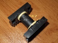
I've started working on smps since 2 days ago , stranded 10x0.15mm wires for primary.
i have some questions about transformer , is this steps are correct :
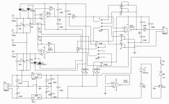
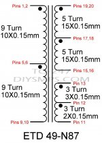
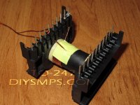
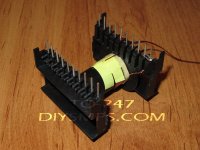
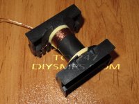
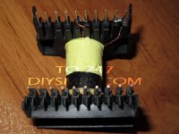
(look at schematic of transformer at attachments)

1-Make 3mm margin from both side of bobbin

2-Primary Section 1 :
Start on pins 1,2 > Winding 9 Turns of 10x0.15mm stranded wires > finish on pins 5,6

3-three Layers of mylar tape


4-Secondary(40v) Section 1 :
Start on Pins 19,20 > Winding 5 Turns of 15x0.15mm stranded Wires > finish on pins 17,18

5-two layers of mylar tape

6-Secondary(40v) Section 2
Start on pins 17,18 > Winding 5 Turns of 15x0.15mm stranded wires > finish on pins 15,16

7-two layers of mylar tape


8-Secondary(24v) Section 1 :
Start on pin 13 > winding 3 turns of 3x0.15mm stranded wires > finish on pin 12

9-two layers of mylar tape

10-Secondary(24v) Section 2 :
Start on pin 12 > winding 3 turns of 3x0.15mm stranded wires > finish on pin 11

11-three layers of mylar tape

12-Primary Section 2 :
Start on pins 5,6 > Winding 9 Turns of 10x0.15mm stranded wires > finish on pins 9,10

13-three layers of mylar tape

14-good job :D

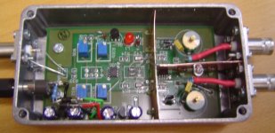
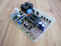
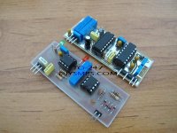
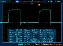
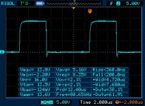
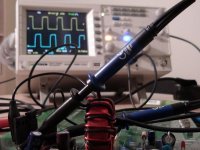
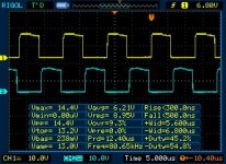
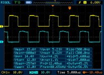
I'm also tested gate driver and over current circuits on the board. results are available on the attachments.
the bad thing about O.C protector is we have to turn smps of to reset the protector. :( any solution ?
 

Attachments

  • Q1.jpg
    Q1.jpg
    99 KB · Views: 233
  • Q2.jpg
    Q2.jpg
    103.7 KB · Views: 200
  • Q1-Vgs.jpg
    Q1-Vgs.jpg
    37.9 KB · Views: 165
  • Q2-Vgs.jpg
    Q2-Vgs.jpg
    37.8 KB · Views: 145
  • Transformer-1.jpg
    Transformer-1.jpg
    84.4 KB · Views: 262

MicrosiM

Administrator
Staff member
TO247


No problem, we are all busy ! :)

Waves looks OK, but I wonder why its showing 61% duty!

Every thing looks normal, go to next step and report back!


Protection circuit is correct, it locks out, not going to reset after.

You can improve it if you like! its not that complex

regards
 

TO-247

New member
No problem, we are all busy !

thanks , indeed we are.

Waves looks OK, but I wonder why its showing 61% duty!

the 61% is -duty. the +duty is about 38% (mosfet on). is it ok ? i know that if the duty is 50% , we haven't any dead time.but i don't know how much duty is acceptable.

Protection circuit is correct, it locks out, not going to reset after.

You can improve it if you like! its not that complex

thanks , the protection circuits are very important for all smps.

______________

I've just finished primary winding (section one). take a look at pictures , what do you think ?
it's so difficult ;ww:
can i start secondary winding (section one) beside primary (section one) ?
do you have any picture of your transformers while winding ?

Thanks
 

Attachments

  • 3mm Margin.jpg
    3mm Margin.jpg
    103.2 KB · Views: 206
  • Pri-Sec1-3.jpg
    Pri-Sec1-3.jpg
    97.7 KB · Views: 183
  • Pri-Sec1-2.jpg
    Pri-Sec1-2.jpg
    95.8 KB · Views: 186
  • Pri-Sec1-1.jpg
    Pri-Sec1-1.jpg
    99.1 KB · Views: 216
  • Pri-Sec1-4.jpg
    Pri-Sec1-4.jpg
    87.4 KB · Views: 181
Last edited:

MicrosiM

Administrator
Staff member
Hello

Duty must be 50% on 50% off, otherwise blow up will occur.

I dont know why you dont make your turns centered in transformer, you can put 20 turns in one layer for primary, then wind all secondary after, this is good also, i tried this method last time with ETD49.

You cant wind using method you have mentioned.


Good luck
 

TO-247

New member
Hi MicrosiM

Duty must be 50% on 50% off,.

it's because my design reference was ludo v.2 circuit.that circuit had some problems.
I've already updated my pwm generation circuit to ludo version 3 design.now , it can reach 45% duty.
do you measure your sg3525 based circuit's duty cycle ? do you have any pics of that ? i have one of your scope pics on my computer.-)

otherwise blow up will occur
!!!:
can you explain more about this ? i think lower duty cycles will decrease output voltages.
 

Attachments

  • DSC00512.jpg
    DSC00512.jpg
    54.4 KB · Views: 93
  • 600W SMPS-V.2.0.pdf
    357 KB · Views: 397
  • Out (1).jpg
    Out (1).jpg
    44.6 KB · Views: 98
  • Out (2).jpg
    Out (2).jpg
    42.5 KB · Views: 85
Top