"TO-247" First Project - 600W SMPS"

MicrosiM

Administrator
Staff member
MicrosiM ,

sorry , i forgot to ask one question...

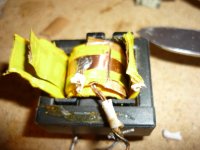
what is the good value for transformer's temperature ? is it good to have 36.5ºC after 5 minutes with 60w load ?
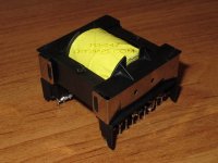
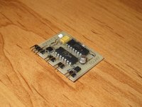
a few minutes later , i'm going to test smps with 200w bulb. position of sensor was attached.

Regards

Thats almost OK


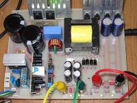
Now when make sure that your SMPS is stable, like loading it with 500W for a few minutes WHILE monitoring waves + heat for all.

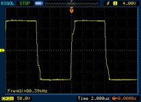
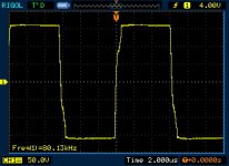
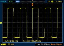
You have to show me waves:-

1- Across primary of your ETD49, LOADED, and NOT Loaded
2- Across series CAPACITOR while SMPS is LOADED 600 ~ 800 W


You may change your heat sink to a bigger one at this stage, I advice you to put another piece of heat sink on TOP of the Mosfets, Sandwich them!,

Dont be Afraid, SMPS will heat... and if your setup is OK hitting the 60 ~75C of Mosfets Heat Sink will be fine!

Watch tempretures, and make sure that you stay away at the testing stages.. If things are fine, then you are safe!

Good luck!
 

TO-247

New member
Another no load test !

MicrosiM ,

Now when make sure that your SMPS is stable
how can i make sure ? please look at my new temperature test results , thanks.
loading it with 500W for a few minutes WHILE monitoring waves + heat for all.

sorry , but i didn't understand which waves or temp you want to know exactly. for example , Vds or Vgs ? or that waves you said in your last post ;

1- Across primary of your ETD49, LOADED, and NOT Loaded
2- Across series CAPACITOR while SMPS is LOADED 600 ~ 800 W

You may change your heat sink to a bigger one at this stage, I advice you to put another piece of heat sink on TOP of the Mosfets, Sandwich them!,

thanks , but i don't have more heat sinks like those. -)
Dont be Afraid, SMPS will heat... and if your setup is OK hitting the 60 ~75C of Mosfets Heat Sink will be fine!

you know , i'm not afraid of heat , but i afraid of missing my TO-247s :D

anyway , i did another no load test , because i wanted to measure transformer's temp with more focus , here is results :

Mosfets Temp @ t=0 , = 26ºC
Mosfets Temp @ t = 30Mins , = 45ºC

Transformer Temp @ t=0 , = 28ºC
Transformer Temp @ t=30Mins , 46ºC

do you think they are ok ?
also here is a picture after 30 minutes.
 

Attachments

  • 600W SMPS - After 30mins - No Load-1.jpg
    600W SMPS - After 30mins - No Load-1.jpg
    147.8 KB · Views: 246

MicrosiM

Administrator
Staff member
I want to see DS Waves while SMPS is loaded 500W, in addition to the below waves

1- Across primary of your ETD49, LOADED, and NOT Loaded
2- Across series CAPACITOR while SMPS is LOADED 600 ~ 800 W

I want to see Mosfets tempreture, Make sure when tempreture reaches 60C that waves across DS is CLEAN square, if they start to shake, SHUT DOWN smps immediatlly.

If they are Stable, and CLEAN square at 60 ~ 65C, then you are done!

Your tempreturs looks OK, but SMPS needs tuning!

Do those tests, ENJOY your SMPS!
 

padmanabhan

New member
Goodevening Dear microsim,


i ref to the SCH of 600W smps using SG3525 [by TO - 247 diysmps Member*], here pin 1 is not given the feedback voltage, kindly explain me how the feedback works, possibly i may not be aware of the new technik.

regards padmanabhan.k
 

TO-247

New member
Hi MircrosiM ,

for two week , i'm working to improve some part of my smps like transformer (winding with 30 or more stranded 0.1mm wire for both primary and secondary) and also designing new pwm control board.
the value of main capacitors also changed to 4x820uf for less inrush current (4x1200uf was not suitable for 600w smps) and the 5 Ohms NTC changed to 10 Ohms one.

before that changes , the smps was tested with 80w output power , and primary's voltages were attached.
it's so difficult to find a load with 300w or more power consumption !

about transformer , as i said , I've started winding with new properties. because i think 10x0.15mm wire not enough for this smps. for example , in quasar smps , i saw many peoples used 120x0.1mm litz wire , so why we aren't use more stranded wire ? -)


i ref to the SCH of 600W smps using SG3525 [by TO - 247 diysmps Member*], here pin 1 is not given the feedback voltage, kindly explain me how the feedback works, possibly i may not be aware of the new technik.

that's because it's a fixed pulse width smps or unregulated smps. therefore ,it doesn't need feedback from output voltages or something like this.
 

Attachments

  • 80W Load - across primary - 200w series bulb.jpg
    80W Load - across primary - 200w series bulb.jpg
    29.1 KB · Views: 73
  • 80W Load - across primary - without 200w series bulb.jpg
    80W Load - across primary - without 200w series bulb.jpg
    29.3 KB · Views: 59

MicrosiM

Administrator
Staff member
Good Waves!

I never told dont use more strands, the more strands are better in terms of heat and many other issues, but for those people who cannot find the proper wire, they can do strands, either you can use solid wire. it will be perfect for audio use.

+ Litz wire is not the ultimate solution!

See my video loading ETD49 with normal cooper wire, very normal voltage drop! for unregulated SMPS!

I have seen cooper wire used into commercial SMPS units powering audio amplifiers, without any issues!

Regards
 

TO-247

New member
thanks MircrosiM ,

Good Waves!
for 80w load yes..i should load smps more..
can you show me normal wave for across primary @ 500w load ? and please for series capacitor too.

the more strands are better in terms of heat and many other issues

how about copper foil ? can i use copper foil instead of stranded wires like attached photo ?

See my video loading ETD49 with normal cooper wire, very normal voltage drop! for unregulated SMPS!

how much voltage drop is acceptable for unregulated smps ?

Regards
 

Attachments

  • Copper foils.jpg
    Copper foils.jpg
    170 KB · Views: 246

MicrosiM

Administrator
Staff member
You should inspect the waves your self! Thats the fun! dont waste it

Cooper foil is excellent for SMPS also, give it a try


Good luck, and waiting for more results..
 

TO-247

New member
New Transformer

some pictures of my new transformer
Primary : 120x0.1mm (homemade !)
secondary : 27mmx0.1mm copper foil

Regards
 

Attachments

  • 0.1mmx27mm Copper Foil.jpg
    0.1mmx27mm Copper Foil.jpg
    62.9 KB · Views: 200
  • New Transformator-2.jpg
    New Transformator-2.jpg
    84.5 KB · Views: 146
  • New Transformator-1.jpg
    New Transformator-1.jpg
    78.5 KB · Views: 164
  • HM-120x0.1mm.jpg
    HM-120x0.1mm.jpg
    54.9 KB · Views: 182

TO-247

New member
I will waiting for it complete..
and share it mr.

well , i never going to share this SMPS project , because it contain many faults in pcb design and also schematic. you should wait for new one or it's better to do it yourself.
 

vorezky04

New member
well , i never going to share this SMPS project , because it contain many faults in pcb design and also schematic. you should wait for new one or it's better to do it yourself.

Why??
What the schematic from microsim is false?
 

TO-247

New member
What the schematic from microsim is false?

No , my own schematic had some problem.most of problems were from pcb. but if you want to know last changes , refer to MicrosiM's last schematic in ludo's topic.
 

TO-247

New member
So...after a while..my new smps is ready for some serious tests..
here is two picture that show you my new PCBs..
also a picture from voltage across transformer..very good , no spikes.
mosfets temperature after 30 Minutes about 45ºC (with this small heatsink and no load).

please don't tell me about sharing this project.if you want to make a smps , it's better to do it yourself and do some improvement.
also you can get helps from this topic or ludo's topic. it's not a simple diy electronic project for sharing. if you can't , try commercial kits at first.
 

Attachments

  • 600W.MK2.1.jpg
    600W.MK2.1.jpg
    111.1 KB · Views: 322
  • PWM.C.2.jpg
    PWM.C.2.jpg
    99.8 KB · Views: 247
  • VT-1.jpg
    VT-1.jpg
    32.5 KB · Views: 161
Last edited:
Top