Hi !!
Hi guys..:02.47-tranquillity:
after a long time..because don't have enough time to do more researches..

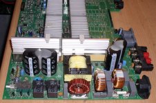
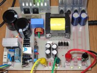
MicrosiM , my last smps board have some problems which i listed some of them below and i wish i could do a better job next time -)
- input connector make some problems => change with tab connector
- input rectifier gets warm => change with 25A type at minimum + larger heatsink
- using higher rating fuse and its holder
- change the design with quasi-resonant type but without series coil , for having better operation
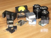
- low continuous output power = changing switching transistor with IGBTs , use EE55 core , change output diodes as well. my goal is about 1~1.5KW max.
- maybe using low profile components to get less height.
- 3 vertical mounted board ! => using one for all function
- changing OCP-SCP protection if its not gonna be very hard to design.
- output voltages goes higher like 75~90v and add more aux outs.
- if it's possible , change PCB routing for having less EMI and better performance.
- decrease the switching frequency to have less switching loss if it doesn't make any problem !
______________
That coil is needed into resonant SMPS circuits in order to add more leakage inductance to the transformer primary. its same SMPS you have just made, only thing is that inductor, however.
Resonant can be done without the series inductor.
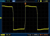
If you show me WAVE across your series capacitor with transformer will tell you more.
Wave WHILE SMPS is loaded at least 500W.
so , lots of work should i do...but for first step , i have some question , sorry for takes your time
1- can i use your excel file for calculation new transformer ? because i changed type of smps into QR type.
2- how can i learn more about half-bridge QR type smps ? i want to design one of them but without series coil..
Thanks MicrosiM for all helps you provide