You are using an out of date browser. It may not display this or other websites correctly.
You should upgrade or use an alternative browser.
You should upgrade or use an alternative browser.
Maxter 3600
- Thread starter aldemarar
- Start date

mrbuttercup
New member
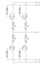
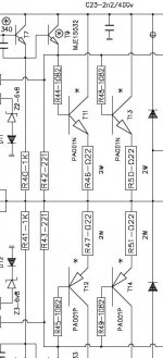
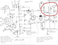
good day michelle do you have a schematic diagram of thi step dirver
thanking you
leo
thanking you
leo
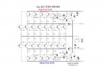
Pls use mjl(on)transistors for the outputs
hi chesta
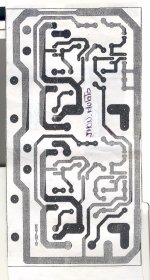
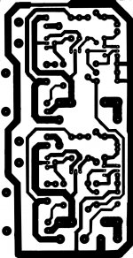
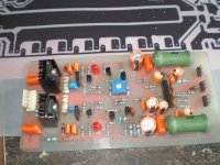
do u have the pcb of this amp.
how many watts of this amp into 8ohm.
ravpreet420
Member
Hi michelle
Plz share pcb in pdf format
Plz share pcb in pdf format