"TO-247" First Project - 600W SMPS"

MicrosiM

Administrator
Staff member
Hi MicrosiM


it's because my design reference was ludo v.2 circuit.that circuit had some problems.
I've already updated my pwm generation circuit to ludo version 3 design.now , it can reach 45% duty.
do you measure your sg3525 based circuit's duty cycle ? do you have any pics of that ? i have one of your scope pics on my computer.-)


!!!:
can you explain more about this ? i think lower duty cycles will decrease output voltages.

This is not a regulated SMPS, so you should have 50% duty, or 49% Duty.

In regulated SMPS its fine to change duty in reference to the SG3525.

I will send you some pictures of scope today, I fixed an amplifier days ago with SMPS, and I have 42% duty!! after replacing some parts things fixed.

Please check again.
 

TO-247

New member
I will send you some pictures of scope today, I fixed an amplifier days ago with SMPS, and I have 42% duty!! after replacing some parts things fixed.

Please check again.

ok , thanks , I'll keep you posted.
 

TO-247

New member
please update your schematic of SG3525 to the one I have uploaded today
thanks , but that circuit didn't solve my problem.i don't know why.:"::

i think the problem isn't about schematic or something like this.

i did some simple test about sg3525 , i saw some elements of circuit do nothing ! so i removed some caps and resistors.i know that elements must be useful in regulated smps.
also , i saw when we increase the output frequency , the Dutycycle decrease. in picture 3 from left , you can see test result about 44Khz with CT=100pf and RT= 100k (adjusted for 44Khz). then i increased the frequency to 80Khz and you can see the dutycycle decrease from 48.2 to 46.8(picture 4 from left).
in last one , you can see test result for CT=1nf and RT=20k(adjusted for 80Khz). the dutycycle decrease from 46.8 to 43.5.

please do some test like me (simple circuit on attachments) and keep me posted.(about Duty%)

i don't know why others don't care !! i should thanks MicrosiM because he just help others. other users just want to have PCB layouts ! ::SD
i like to do something like this , because we work on electronics for learning things , not for do some projects and then forget every things about that.

i'm also going to buy new SGs for future tests.i have this SG since 2-3 years ago !
 

Attachments

  • 100pF-100K-44KHz.jpg
    100pF-100K-44KHz.jpg
    41 KB · Views: 155
  • 1nF-20K-80KHz.jpg
    1nF-20K-80KHz.jpg
    41.4 KB · Views: 100
  • 100pF-100K-1.jpg
    100pF-100K-1.jpg
    101.1 KB · Views: 155
  • 100pF-100K-80KHz.jpg
    100pF-100K-80KHz.jpg
    41.8 KB · Views: 133
  • SG3525-Test Circuit.jpg
    SG3525-Test Circuit.jpg
    46 KB · Views: 354
  • 1nF-20K-1.jpg
    1nF-20K-1.jpg
    99.6 KB · Views: 124
Last edited:

MicrosiM

Administrator
Staff member
I will do some tests now and report back as soon as possible

Please try to make identical copy of schematic I have posted


Regards
 

MicrosiM

Administrator
Staff member
TO247

See attached waves taken from my commercial SMPS unit pre release, they are from exact circuit I gave you.


Duty is almost 50% wih 0.1 ~ 0.2 Tolerance


Please advice your status
 

Attachments

  • cobra12000.rar
    147.4 KB · Views: 770

TO-247

New member
I'm confused ! :(

Please try to make identical copy of schematic I have posted

i will do that after buying new SGs.

See attached waves taken from my commercial SMPS unit pre release, they are from exact circuit I gave you.
thanks , do you have any picture of SG3525 section from your smps board ?
do you think the type of components are important ? for example using tantalums instead of electrolytes.

a video of testing :

[video=youtube;49Xjc9EPAQM]http://www.youtube.com/watch?v=49Xjc9EPAQM[/video]
 

MicrosiM

Administrator
Staff member
Really, that looks strange!

you should keep trying, I think it could be some things simple to look for.

Please use electo capacitors, stick to original circuit, and keep trying

Not sure if SG makes that kind of problem, it could be any thing causing this

What is your voltage supply?
 

dudaindc

Analog Ears!
After watching tt=he video, two questions come to mind:

Do you get this strange behavior with another SG3525?

Could the one you are using be defective? -)

Cheers!
 

TO-247

New member
News !

Do you get this strange behavior with another SG3525?

yes , but actually with SGs , not KAs.
What is your voltage supply?

it was 14.6v , but i tested with higher voltages like 18 and that problem was still available.

_____________________

Up with some good and bad news !!

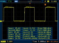
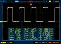
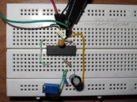
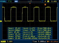
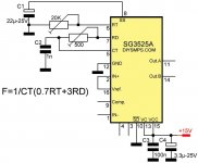
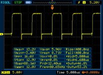
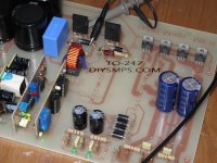
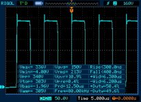
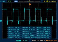
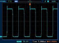
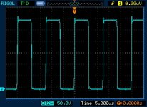
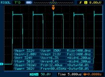
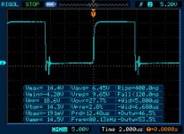
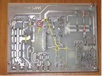
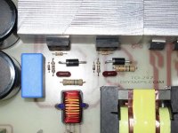
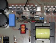
I improved my pwm board , but before that , I did some test with a lot of circuits and with new SGs or KAs , finally i could get maximum duty about 46.8 from KA3525 ( about 46 at mosfets gates). also if i
connect pin 7 (Rd) of SG to pin 5 directly , i can get maximum dutycycle about 47 or a bit higher in gates.
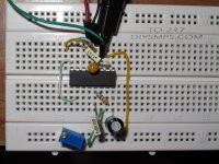
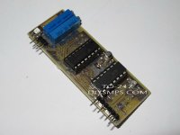
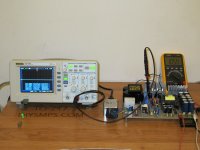
I'm also tested new MicrosiM schematic , but it hadn't any differences whit my own schematic(specially in dutycycles) . you can find some picture of edited pwm board and testing progress.

ok , lets go for good news :) :
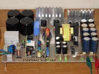
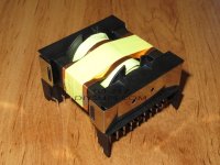
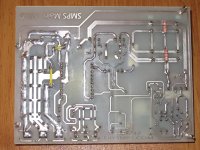
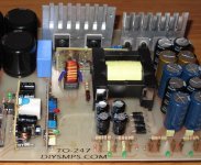
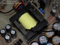
i didn't care of that problem , I finished the transformer's winding and i think that windings just fit on the half of bobbin. so I've added more mylar tape layers at the end !!

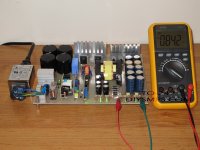
when i finished windings , I decided to test the smps.
at first , i put a 200w bulb in series with one of AC lines and i connected a multimeter to +/-40v output section for reading the output voltages. then , i turned the power on and i became so happy like this : :D because of no fault and enough output voltages around 84v.also i did some test on +/-24v section and that was really nice , had output voltages around 49v.

Here is two video while testing the smps :

First Turn On :
[video=youtube;adtoJ5d0OIU]http://www.youtube.com/watch?v=adtoJ5d0OIU[/video]

Output voltages testing :
[video=youtube;a3HfkdjXEt8]http://www.youtube.com/watch?v=a3HfkdjXEt8[/video]

then , i decided to apply some loads at the 80v outputs , but when i connected a 60w bulb to the outputs , the output voltages decrease from 84 to 78v !!
after that , when i disconnected the mains , i touched the mosfet's heatsink and it was so hot !
is it ok with a 200w bulb series with the input or not ?! :confused:

today , i bought two larger heatsink and also two small thermometers for future testing.
MicrosiM , please tell me some notes about testing progresses of a smps.
can i connect my smps directly to AC lines ? :x:
can i check Vgs of mosfets with scope ?

Thanks.
 

Attachments

  • 600W SMPS - U.T - 1.jpg
    600W SMPS - U.T - 1.jpg
    104.1 KB · Views: 231
  • PWM-1.jpg
    PWM-1.jpg
    66.1 KB · Views: 219
  • 600W SMPS - U.T - 2.jpg
    600W SMPS - U.T - 2.jpg
    88.9 KB · Views: 172
  • PWM-3.jpg
    PWM-3.jpg
    41.2 KB · Views: 158
  • 600W SMPS - ETD-49 Finished.jpg
    600W SMPS - ETD-49 Finished.jpg
    89.4 KB · Views: 176
  • PWM-2.jpg
    PWM-2.jpg
    100.7 KB · Views: 189
  • 600W SMPS V2.2.pdf
    354.3 KB · Views: 875

MicrosiM

Administrator
Staff member
To247

Dear TO-247


I am really impressed with your setup, and how organized it is + a clean PCB productions + Nice transformer, On the other hand you should accept what you will hear, my personal comments at your PCB layout, specially after I saw your scope picture. lets start with points.


1- You cannot connect your SMPS (At this stage) to the 220VAC line, specially if you are getting heat quickly, I need to know how fast the MOSFETS heats up, and do they heat with LOAD or without LOAD?

2- Connect your SMPS with 200W in series lamp, (SMPS NOT LOADED) and sense the heat sink tempreture, and report this point. its normal to have 30 ~ 40C with no load. dont forget that heat sink is small for final stage, but DONT change it, keep using it for testing purposes.

3- Show Waves for each Mosfet (SMPS NOT LOADED) SG, SD for each Mosfet Alone please.

4- I dont know about the duty cycle issue, But if you have an access to another scope, give it a try !!

5- Resistor value for G of Mosfets?

6- Please show me PCB image from bottom, have to see routing for GND also.

Bad thing you should know is the distance from the DRIVER chip to the Mosfets are TOO LONG!, and this is a MAJOR problem :(

I told Ludo once about this issue, and he modified his own PCB in the None released version of the SMPS :( , and he had a Robust results.

Dont worry, we will try to make things work with what we have, dont ever give up into making a SMPS. :UP:

This is for now, please report back..


Regards

Use isolation transformer when testing SMPS with scope, While its connected to the 220VAC line. like SG, SD of Mosfets. Nasty surprises will ocure if you dont follow my instructions :x:


Like, but not limited to:-

1- Unknown lethal results

2- Your oscilloscope will die, in any minute.

3- You may not live to regret what you have done!
 

TO-247

New member
Hi MicrosiM ,

I am really impressed with your setup, and how organized it is + a clean PCB productions + Nice transformer, On the other hand you should accept what you will hear, my personal comments at your PCB layout, specially after I saw your scope picture. lets start with points.

the best answer i can say is THANKS , but you should know ; if we can make smps , that's because you help us in this way.writing a lot of useful notes , giving helps and sharing results and your experiences are some of your activities in this forum. for example , if i didn't know how to use scope in smps measurements , i could destroy it in a few seconds or many other examples like that. at the end , i would like to say : THANKS MicrosiM :cool:

__________________________

1- You cannot connect your SMPS (At this stage) to the 220VAC line, specially if you are getting heat quickly, I need to know how fast the MOSFETS heats up, and do they heat with LOAD or without LOAD?

2- Connect your SMPS with 200W in series lamp, (SMPS NOT LOADED) and sense the heat sink tempreture, and report this point. its normal to have 30 ~ 40C with no load. dont forget that heat sink is small for final stage, but DONT change it, keep using it for testing purposes.

i did a temperature test with two thermometers and without any loads. as you can see in the video , in only 4 Minutes , the temperature of mosfets could reach to around 50ºC . is it ok ? what do you think ?

[video=youtube;UTpW1rNHuJQ]http://www.youtube.com/watch?v=UTpW1rNHuJQ[/video]

3- Show Waves for each Mosfet (SMPS NOT LOADED) SG, SD for each Mosfet Alone please.
please take a look at attachments. i measured Vgs and Vds of each mosfet.
this short video taken while doing this test :

[video=youtube;DBFRrERbQ_c]http://www.youtube.com/watch?v=DBFRrERbQ_c[/video]

4- I dont know about the duty cycle issue, But if you have an access to another scope, give it a try !!
i'm also tested the outputs of SGs with my DMM , result was the same as my scope.
5- Resistor value for G of Mosfets?
it's 10 Ohms , 0.5w

6- Please show me PCB image from bottom, have to see routing for GND also.

it's available on the attachments.
Bad thing you should know is the distance from the DRIVER chip to the Mosfets are TOO LONG!, and this is a MAJOR problem

I told Ludo once about this issue, and he modified his own PCB in the None released version of the SMPS , and he had a Robust results.

i saw your notes in ludo's topic , but i think my design was ok -) next time , I'm going to resolve this problem.
Dont worry, we will try to make things work with what we have, dont ever give up into making a SMPS.

thanks MicrosiM , if you help us , we'll never give up in this way :D

3- You may not live to regret what you have done!

so...i passed one of dangerous levels of developing a smps...
 

Attachments

  • Test-1.jpg
    Test-1.jpg
    72.1 KB · Views: 76
  • Low Side - Vds - 1.jpg
    Low Side - Vds - 1.jpg
    39.5 KB · Views: 94
  • High Side - Vgs.jpg
    High Side - Vgs.jpg
    40.3 KB · Views: 79
  • Low Side - Vds - 2.jpg
    Low Side - Vds - 2.jpg
    31.5 KB · Views: 73
  • High Side - Vds - 1.jpg
    High Side - Vds - 1.jpg
    30.5 KB · Views: 67
  • High Side - Vds - 2.jpg
    High Side - Vds - 2.jpg
    39 KB · Views: 66
  • Low Side - Vgs.jpg
    Low Side - Vgs.jpg
    38.2 KB · Views: 73
  • PCB-Bottom.jpg
    PCB-Bottom.jpg
    168.5 KB · Views: 243

MicrosiM

Administrator
Staff member
There are SPIKES

and they are danger! thats why Mosfets heats very fast, 50C in 4 minutes is NOT ok
Duty not normal

Will figure out things, will post soon
 

MicrosiM

Administrator
Staff member
Mosfets will heat due that SPIKE across S+D

TO-247

To tell you truth, after seeing your PCB layout, your SMPS should work!

Please see attached image, and cut PCB track where indicated by yellow, and connect to the point directly using external wire, 2mm.

Whats that pin connected to GND? ( indicated by RED color)

Please try to show bigger pictures of measurements, + your video is not clear, remove measurements screen when doing so please.

Remove your snubbers if they are installed. and CHECK waves

BAT48?? where did you get that from? please try using 1N4148 or MUR160. schottky? why?
Replace those diodes before doing any thing... Before cutting PCB tracks

please Use MUR460 across DS of each Mosfet.

Please report back results
 

Attachments

  • PCB-Bottom.jpg
    PCB-Bottom.jpg
    94.9 KB · Views: 229

TO-247

New member
MOSFETS are Cool now...

Hi MicrosiM , thanks about all notes.
Please see attached image, and cut PCB track where indicated by yellow, and connect to the point directly using external wire, 2mm.

i fixed that problem , take a look at attachments.

Whats that pin connected to GND? ( indicated by RED color)

it was one lead of 5.6 ohms resistor , which connected to low side mosfet's SOURCE. i attached two picture of mosfets section on the board , that will show you all things better.

Please try to show bigger pictures of measurements, + your video is not clear, remove measurements screen when doing so please.

what's exactly you want to visit ? in this test , I've taken some picture of scope's display with camera and also some of them weren't taken with measurements menu.

Remove your snubbers if they are installed. and CHECK waves

I removed those capacitors and 5.6Ohms resistor and then i did some new test.

BAT48?? where did you get that from? please try using 1N4148 or MUR160. schottky? why?
Replace those diodes before doing any thing... Before cutting PCB tracks

sorry for that , it was my mistake -) i thought faster is better !!
i fixed that problem as well as snubbers. maybe i'm going to replaced 4148s with MUR120s.

please Use MUR460 across DS of each Mosfet.
thanks , also you can find those diodes in my older photos.

in my last post , where you can find Vds of mosfets , also you can find the dutycycle is about 50% or more for each mosfets , but i thought it wasn't acceptable (because of over-lapping problem in bridge and one of important reasons for high temp.) then i checked Rd of 3525 (dead-time setting resistor) , it was about 10 Ohms , i set Rd around 100 Ohms (like your new schematic),however when i checked Vgs of each mosfets again , i could see the duty decreased about 2%.

after every things changed , when i did some test whit scope , i could get very good result for that heating problem. for example , when i turned the smps on , the temperature was about 23.8ºC and after 7 minutes , it was about 26.8 ºC .
here is a video :

[video=youtube;iMniL2sjW1A]http://www.youtube.com/watch?v=iMniL2sjW1A[/video]

but another bad things are :
1- the output voltages decrease about 1.5v per rail because of dutycycles (now they're about 49.2% or a little more).
2-as you can see on the photos , spikes are still available , please help me to remove them.

all the best , DIYSMPS :)
 

Attachments

  • High & Low Sides Voltages.zip
    1.7 MB · Views: 550
  • Mosfets-Before.jpg
    Mosfets-Before.jpg
    111.7 KB · Views: 136
  • PCB - Bottom - New.jpg
    PCB - Bottom - New.jpg
    151.1 KB · Views: 129
  • Mosfets - After.jpg
    Mosfets - After.jpg
    86.6 KB · Views: 141
  • 600W SMPS V2.3.pdf
    348.4 KB · Views: 688

MicrosiM

Administrator
Staff member
That sounds cool


What was the problem with circuit? I mean heat is now gone because?

that 10R resistor is responsible for Dead Time!!! 10R will make Mosfets heat faster!

100R is the BEST choise

Now you should use a snubber, Waves loos better now

You can start with 10R + 470PF 1KV as a start, and see if waves gets better.

Voltage drop is normal, now

Load SMPS with 200W for 10 minutes, and see what happens, while you are monitoring


Regards
 

TO-247

New member
I mean heat is now gone because?

1 - Rd changed to 100 Ohms (dead time increased)
2 - Ground routing changed
3 - Replacing BAT48s
Now you should use a snubber, Waves loos better now

You can start with 10R + 470PF 1KV as a start, and see if waves gets better.

ok , thanks


Load SMPS with 200W for 10 minutes, and see what happens, while you are monitoring

do this test with 200w series bulb ? or directly connected mains ?
 

MicrosiM

Administrator
Staff member
no

Use bulb in series, and connect 100 ~ 300W load, and watch heat of all parts, WHILE monitoring waves for 5 minutes

If all is OK, then connect directly to 220VAC line,(Now you can but the lamp in place of the NTC) load it with 500W , and monitor waves (ISOLATE SCOPE)

Please report back...
 

TO-247

New member
Some important modifications !

Hi MicrosiM

I'm not load smps yet..because i'm tried to make smps board better ! like moving pwm board close to the mosfets or testing snubber circuits.

for snubber , i tried 47 Ohms resistor which in series with 470pf 500v capacitor at primary of transformer. it has good result on Vds.
i measured Vgs and Vds of each mosfet in several scales on scope and results are available on the attachments.

also i did some temperature test again and the results are :
From 26ºC to 39.5ºC after 10 Min.
to 41ºC after 15 Min.
to 41.5ºC after 25 Min.
stable on 41.5ºC

are the results ok ? can i try larger heatsink for loading the smps ?
I'm also attached last version of schematic which i used.
 

Attachments

  • Mosfets-New.jpg
    Mosfets-New.jpg
    175.2 KB · Views: 108
  • PCB-Bottom-New.jpg
    PCB-Bottom-New.jpg
    162.3 KB · Views: 116
  • New - PCB.jpg
    New - PCB.jpg
    116.3 KB · Views: 130
  • 600W SMPS V2.4.pdf
    348.3 KB · Views: 527
  • results test-4.zip
    98.6 KB · Views: 244
Last edited:

TO-247

New member
MicrosiM ,

sorry , i forgot to ask one question...

what is the good value for transformer's temperature ? is it good to have 36.5ºC after 5 minutes with 60w load ?
a few minutes later , i'm going to test smps with 200w bulb. position of sensor was attached.

Regards
 

Attachments

  • Sensor-t.jpg
    Sensor-t.jpg
    95.1 KB · Views: 112
Last edited:
Top